68 EDGE Pro Ti CNC Instruction Manual 807660
Installation
Encoder connection
Encoder connection
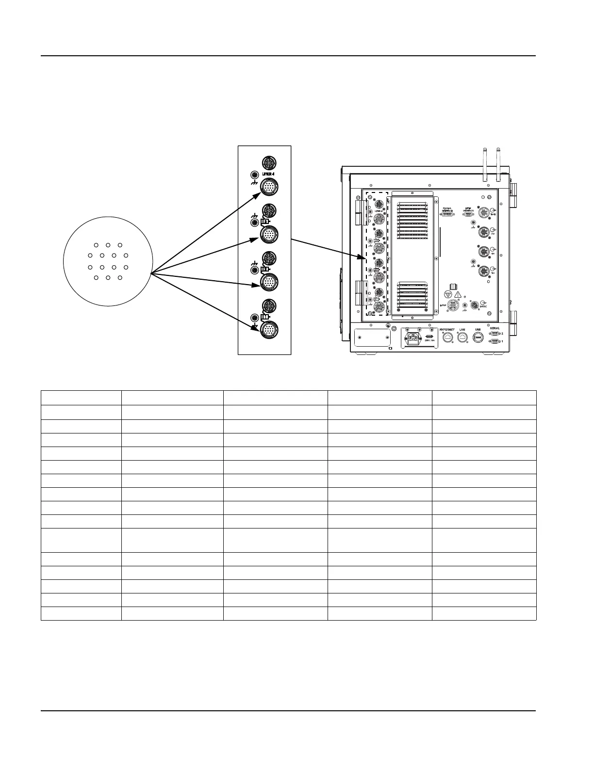
Install the encoder cables between the Axis 4 encoder connector and the encoder connector on the Sensor Ti and
between the Axis 3, Axis 2, and Axis 1 motor connectors on the rear of the EDGE Pro Ti and the motor connector on the
remaining axis motors (031143). For more information about the encoder cable, see Encoder cable on page 69.
Figure 30 EDGE Pro Ti encoder interfaces
Table 12 Pinouts for encoder interfaces
Note:
• Only 5 V encoders are supported.
• Hall sensors are used with brushless motors only.
• For optimum noise immunity, cable shields should be connected externally to the CNC enclosure.
Pin no. Axis 4 – Lifter Axis 3 (Dual gantry) Axis 2 (Y or X) Axis 1 (X or Y)
J12 J11 J10 J9
1 (Red) +5 V +5 V +5 V +5 V
2 (Black) Ground Ground Ground Ground
3 (White) Axis 4A Axis 3A Axis 2A Axis 1A
4 (Black) Axis 4A\ Axis 3A\ Axis 2A\ Axis 1A\
5 (Green) Axis 4B Axis 3B Axis 2B Axis 1B
6 (Black) Axis 4B\ Axis 3B\ Axis 2B\ Axis 1B\
7 (Blue) Axis 4Z Axis 3Z Axis 2Z Axis 1Z
8 (Black) Axis 4Z\ Axis 3Z\ Axis 2Z\ Axis 1Z\
9 (Yellow) +V Encoder/Hall out
(Maximum 6 V at 30 mA)
+V Encoder/Hall out
(Maximum 6 V at 30 mA)
+V Encoder/Hall out
(Maximum 6 V at 30 mA)
+V Encoder/Hall out
(Maximum 6 V at 30 mA)
10 (Black) Ground Ground Ground Ground
11 (Brown) Encoder/Hall A Encoder/Hall A Encoder/Hall A Encoder/Hall A
12 (Orange) Encoder/Hall B Encoder/Hall B Encoder/Hall B Encoder/Hall B
13 (White) Encoder/Hall C Encoder/Hall C Encoder/Hall C Encoder/Hall C
14 (Red) Shield Shield Shield Shield
Axis 1
13
4
8
1214
11
7
Axis 2
Axis 3
Axis 4 –
Lifter
Encoder connector