56 EDGE Pro Ti CNC Instruction Manual 807660
Installation
System connections
System connections
Cable shield grounds
To minimize electromagnetic and radio frequency interference (EMI/RFI), connect all interface cable shields to the
chassis using the following methods, as appropriate:
• The ground screw on the EDGE Pro Ti enclosure
• The dedicated ground pin on each plastic cable connector (CPC)
• The metal shell on the plasma and lifter cable D-sub connectors should be connected to the cable
shield
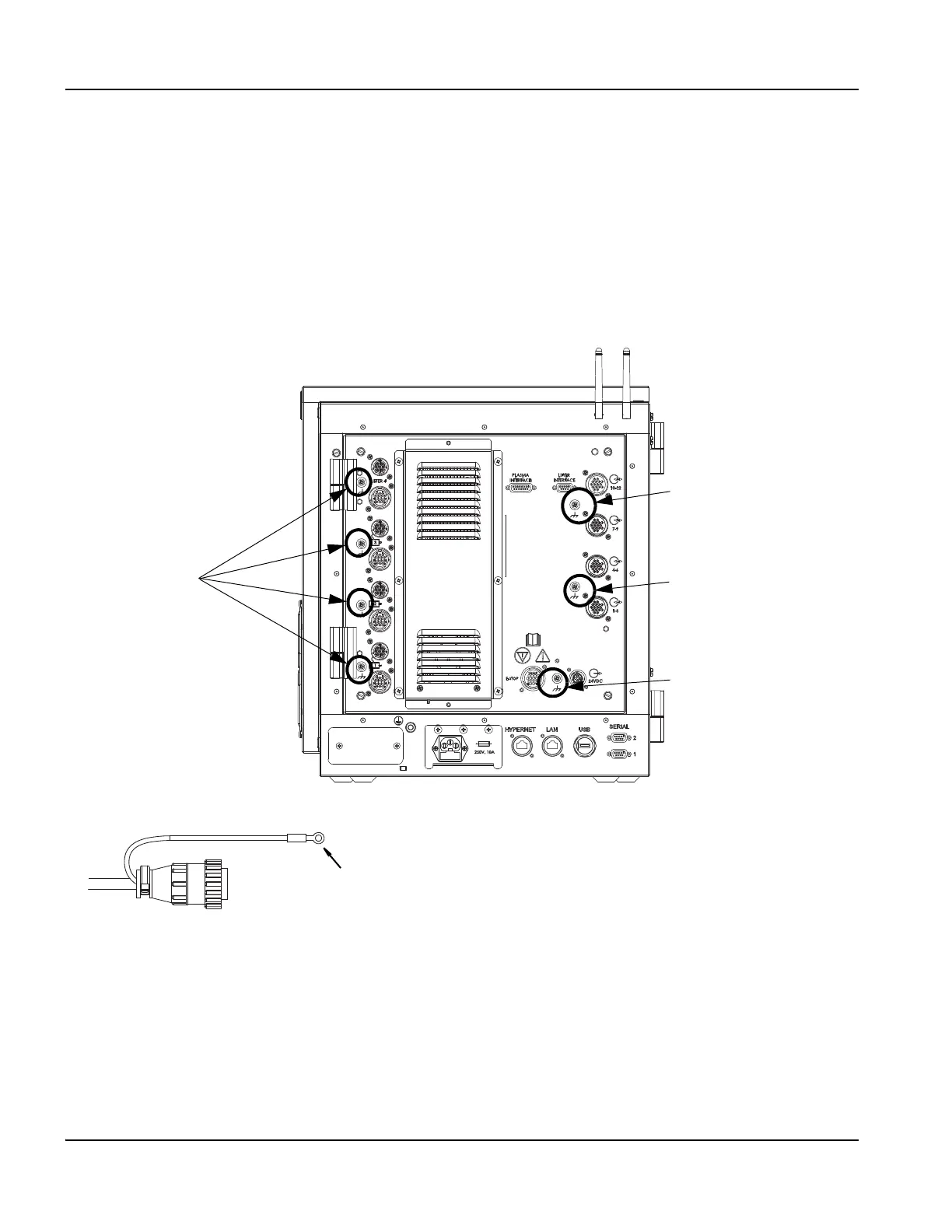
Figure 18 EDGE Pro Ti cable shield ground connections
Cable shield connection
for I/O 7 – 12
Cable shield connection
for I/O 1 – 6
Cable shield connection
for E-stop and 24 VDC
auxiliary power
Cable shield
connections for
motors and encoders
Connect the tab on the cable shield to the cable shield connection.