142 EDGE Pro Ti CNC Instruction Manual 807660
Maintenance and Diagnostics
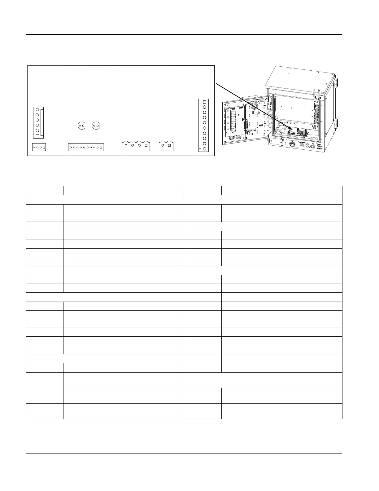
Surge board (141287)
Surge board (141287)
Figure 72 Surge board
Table 44 Pinouts for J1 to J3
Pin no. Signal Pin no. Signal
J1 J4
1 Line 1 1 Line 2, neutral
2 Line 1 ATX 2 Line 1
3 Not connected
J5
4 Not connected 1 E-Stop sense A
5 Not connected 2 E-Stop sense B
6 Not connected 3 60 V Enable A
7 Line 2 MOV 4 60 V Enable B
8 Earth ground
J6
9 Line 1 MOV 1 +24 V
10 Earth ground 2 E-Stop monitor 1A
J2
3 E-Stop monitor 1B
1 Field ground 4 E-Stop monitor 2A
2 +24 V 5 E-Stop monitor 2B
3 Not connected 6 24 V coil 1A
4 Not connected 7 24 V coil 1B
5 Not connected 8 24 V coil 2A
6 Not connected 9 24 V coil 2B
J3
10 Field ground
1 Line 1 ATX
LEDs Color and condition
2 Line 2 Both D3 and D4 must be illuminated to indicate that the Edge Pro
Ti E-stop is satisfied and to enable servo drives and motor activity.
3 Line 1 60 VDC power supply D3 Green. Illuminated when E-stop CPC pins 8 to 9
are closed and relay LS2 has power.
4 Line 2 60 VDC power supply D4 Green. Illuminated when E-stop CPC pins 6 to 7
are closed and relay LS1 has power.