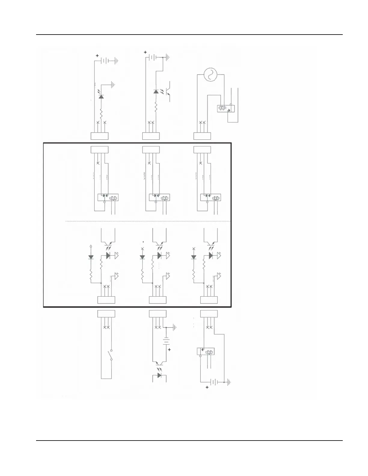
Internal Circuitry
Outputs
Inputs
Example Inputs
External circuitry
Example Outputs
External circuitry
Dry contact inputs
Note: Logic level reversal
Normal sourced inputs
Use external +12 V supply
Dry contact inputs
DIP Switch 1-C closed
Normal sourced inputs
DIP Switch 1-C open
Normal sourced inputs
DIP Switch 1-C open
Use external +12V supply and
normally closed contact
Use external +5 V supply and
normally open contact
Use external 24 VAC and normally
open contact
Normal sourced inputs
Use external +12 V supply
Resistor
Optoisolator
Optoisolator
Relay
Relay SPDT
Relay SPDT
Relay SPDT
Relay
Resistor
External grounds
24 VAC
Switch
12 V
24 V
External ground
12 V
External
ground
Ground
5 V
LED
common
normally closed
normally open
common
normally closed
common
normally closed
normally open
normally open
24 V Field
Ground
Ground
Open
Open
3900
3900
3900
3900
3900
3900
Note:
• To prevent damage, do not apply more than 24 VDC to any optoisolator input and verify the correct signal
polarity.
• Do not exceed the following voltage and amperage ratings through any relay output:
• For outputs 1-12 and Plasma Start: 30 VAC or VDC/1 A. The rating is the same for both AC or DC.
• For the brakes 1-4: 30 VDC/1 A or 30 VAC/0.5 A.
• For Hold Ignition: 30 VDC/10 mA, polarity is important.