EasyManuals Logo

Hypertherm EDGE Pro Ti User Manual

Hypertherm EDGE Pro Ti
166 pages
To Next Page IconTo Next Page
To Previous Page IconTo Previous Page
Page #88 background imageLoading...
Page #88 background image
88 EDGE Pro Ti CNC Instruction Manual 807660
Installation
Lifter interface
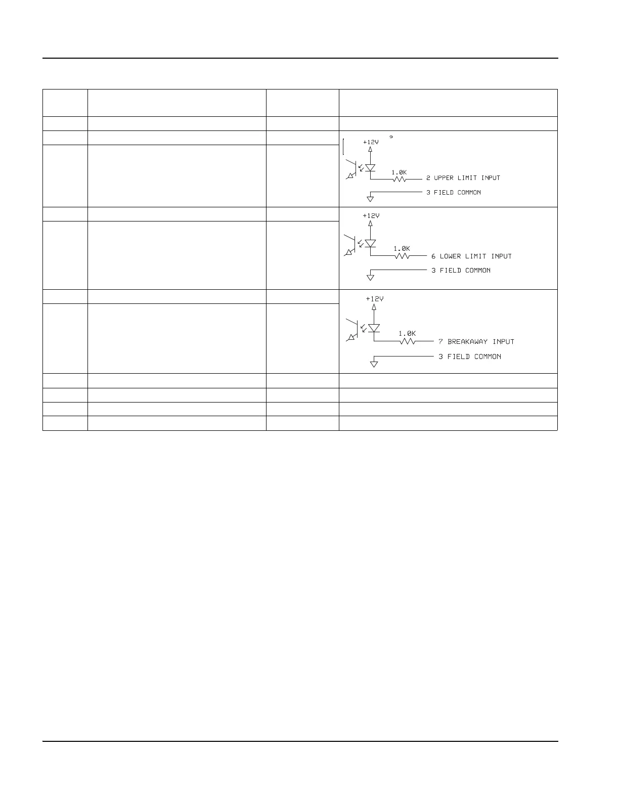
Table 20 Pinouts for the lifter interface
Pin
number
Signal Wire color Dry contact circuit
1 +12 VDC Black
2 Upper Limit switch (shared with input 11) White Normally
open
3 Field Common Red
6 Lower Limit switch (shared with input 12) Blue
3 Field Common Red
7 Breakaway switch Orange
3 Field Common Red
8 Field Common Yellow
4 Nozzle contact -12 V Green
9 Nozzle contact sense Violet
5 Nozzle contact common Brown

Table of Contents

Questions and Answers:

Question and Answer IconNeed help?

Do you have a question about the Hypertherm EDGE Pro Ti and is the answer not in the manual?

Hypertherm EDGE Pro Ti Specifications

General IconGeneral
BrandHypertherm
ModelEDGE Pro Ti
CategoryControl Systems
LanguageEnglish

Related product manuals