EasyManuals Logo

IBM V7000 User Manual

IBM V7000
670 pages
To Next Page IconTo Next Page
To Previous Page IconTo Previous Page
Page #551 background imageLoading...
Page #551 background image
Chapter 12. Host configuration 531
We then added a single device and then had a look at the properties of that device for each
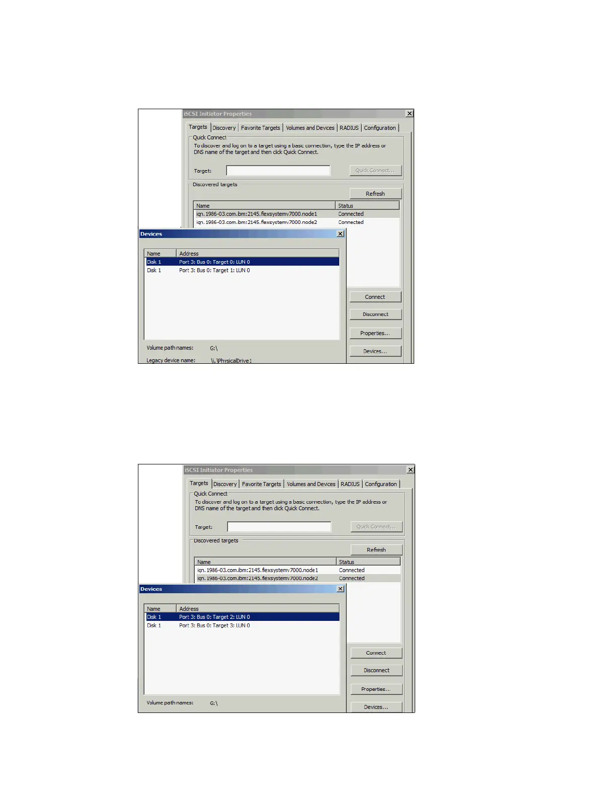
iSCSI target. In Figure 12-30, the first target was highlighted and Devices box clicked.
Figure 12-30 Two ‘Disk 1’s identified on first target
From here, there are two disks of the same name identified as ‘Target 0’ and ‘Target 1’. They
represent two paths, one from each x240 host adapter to the node canister on separate
networks.
From the other path, the iSCSI target of node 2 is shown in Figure 12-31.
Figure 12-31 Two more devices on second target

Table of Contents

Questions and Answers:

Question and Answer IconNeed help?

Do you have a question about the IBM V7000 and is the answer not in the manual?

IBM V7000 Specifications

General IconGeneral
ModelIBM Storwize V7000
Storage TypeHybrid Flash Array
Maximum Capacity1.2PB
RAID Levels0, 1, 5, 6, 10
Connectivity8 Gbps Fibre Channel, 16 Gbps Fibre Channel, 1 Gbps iSCSI, 10 Gbps iSCSI
ManagementCommand-line interface (CLI), Graphical user interface (GUI)
Form Factor2U
Drive Bays12
Maximum Raw Capacity1.2PB
Operating System SupportAIX, HP-UX, Linux, VMware, Windows
Data Reduction FeaturesReal-time Compression, Deduplication
Drive TypesSSD, HDD
ScalabilityScale-up (drive enclosures) and scale-out (clustering) capabilities

Related product manuals