SETTING CHANGES
iTDC
p.115
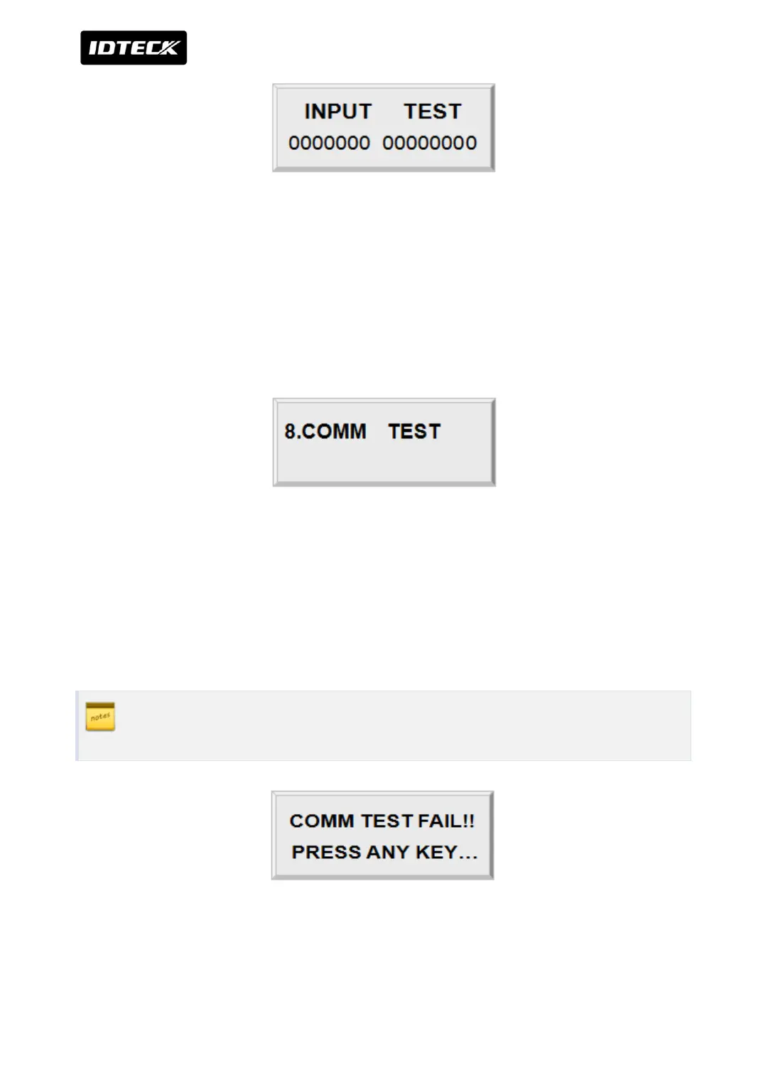
The first 7 digits of the bottom line shows the status of the DIP switch for communication ID
setting of iTDC and “1” indicates the switch ON position and “0” indicates the switch OFF
position. The last 8 digits shows the input status of EIO88 and “0” indicates the input port
open circuit and “1” indicates the input port short to ground level. Press <ESC> key to return
to the set-up menu.
4.8 COMMUNICATION TEST
Before this communication test,
RS232
Connect the RS232-RX and RS232-TX wires together.
RS-422
Connect the Rx (-) and TX (-), Rx (+) and TX (+) wires.
In case of RS422 test, pull out JP3, 4 and short JP5, 6. After the test is done, short
pin1, (or 2,3) of the JP3, 4.
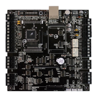
This test is a loop test and iTDC sends a character to TX port and check whether the RX port
receive the character or not. If you have an error, please contact our service facility.