PRODUCT OVERVIEW
iTDC
p.17
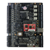
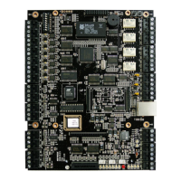
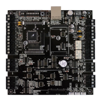
1.1 iTDC/iTDC-SR Board Arrangement Table
No Name Function
1 Board ID
Setting Switch
It’s the switch to set board ID. The board ID is the unique address
for the device.
2 EIO88
Connector
This EIO88 connector is to connect the optional EIO88 expansion
I/O board. iTDC/iTDC-SR can expand 8 input/output by attaching
EIO88 board.
3 Buzzer This is an internal buzzer, which makes beep sounds when keypad
is pressed from the optional keypad and the sound also generates
to notice alarm status.
4 Initialization
Switch
These switches are to initialize user data in the memory. To be
default setting by Initialization, press the two switches
simultaneously then keep pressing more than 2 seconds to initialize
properly.
5 Relay #1 ~
Relay #4
Output Port
These are 4 FORM-C (COM, NO, NC) relay output ports at
DC12~24V, Max 2A current.
6 TTL #1 ~ #3
Output Port
These are 3 TTL outputs. The normal logical state of TTL output is
Low (DC0V) and activates to High (DC5V).
7 RJ-45
Connector
It’s RJ45 connector to connect Ethernet Cable
8 TCP/IP Module
Connector
(IIM100)
This is connector to insert TCP/IP module (IIM100). TCP/IP module
is offered optionally.
9 LED #1 ~ #2 These 2 LEDs indicate status of communication. LED #1 is for RX
status, which blinks when data is normally received from the PC.
LED #2 is for TX status, which blinks when data is transmitted to
the PC after data is processed normally on the PC.
10 RS232 Serial C
ommunication
Port
The iTDC has one of RS-232 communication port for such short
distance individual connection with the PC.
11 RS422 Serial C
ommunication
Port
This is RS422 communication port for such long distance
connection of multiple boards up to 256 units to PC by multi drop
communication. The RS422/ RS232 converter is necessary for
connecting RS422 port to PC.
12 Power Port This is main power port. iTDC is working at DC12V and max
500mA current. (It is applied only when door lock devices, alarms,
sensors and reader is not connected.)