p.44
PRODUCT INSTALLATION
iTDC
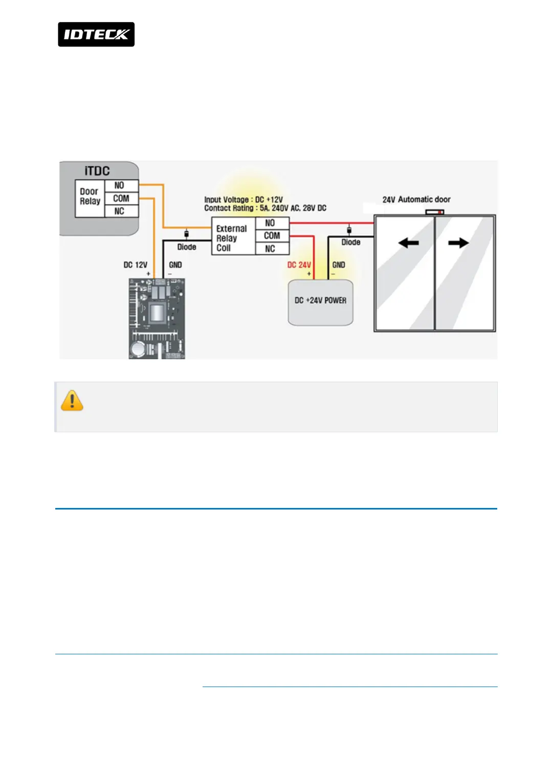
To use 24V door lock or automatic door, wire door lock depending on Power Fail Safe or
Power Fail Secure but, you must connect 24V external relay using separate power supplier as
figure below.
7.4 Wiring for using 24V door lock or automatic door
If you don’t use separate power device or external relay, relay can be destroyed and
it may causes malfunctions.
8 READER WIRING
RF reader can be connected to reader port (READER#1~ READER#4) of iTDC/iTDC-SR.
Depending on number of doors, wiring can be different so follow the table below.
8.1 2-Door Control
For 2-Door Control, a door is connected to external reader for entrance and the other door is
connected to internal reader for exit. Also exit button can be used behalf of internal reader.
Door 1 External
Reader
Reader#1
Connect +12V wire (Red) to +12V of reader#1 port of
iTDC/iTDC-SR main board.
Connect GND (-) wire (Black) to GND of READER#1 port of