PRODUCT INSTALLATION
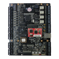
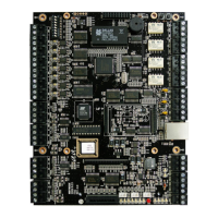
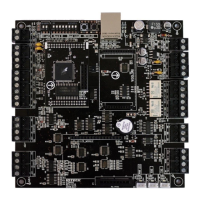
iTDC
p.45
iTDC/iTDC-SR main board.
Connect D0 wire (Green) to D0 of READER#1 port of iTDC/iTDC-SR
main board.
Connect D1 wire (White) to D1 of READER#1 port of iTDC/iTDC-SR
main board.
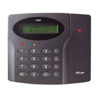
Internal Reader
Reader#2
Connect +12V wire (Red) to +12V of READER#2 port of
iTDC/iTDC-SR main board.
Connect GND (-) wire (Black) to GND of READER#2 port of
iTDC/iTDC-SR main board.
Connect D0 wire (Green) to D0 of READER#2 port of iTDC/iTDC-SR
main board.
Connect D1 wire (White) to D1 of READER#2 port of iTDC/iTDC-SR
main board.
Door 2 External
Reader
Reader#3
Connect +12V wire (Red) to +12V of READER#3 of iTDC/iTDC-SR
main board.
Connect GND (-) wire (Black) to GND of READER#3 of
iTDC/iTDC-SR main board.
Connect D0 wire (Green) to D0 of READER#3 of iTDC/iTDC-SR
main board.
Connect D1 wire (White) to D1 of READER#3 of iTDC/iTDC-SR
main board.
Internal Reader
Reader#4
Connect +12V wire (Red) to +12V of READER#4 port of
iTDC/iTDC-SR main board.
Connect GND (-) wire (Black) to GND of READER#4 port of
iTDC/iTDC-SR main board.
Connect D0 wire (Green) to D0 of READER#4 port of iTDC/iTDC-SR
main board.
Connect D1 wire (White) to D1 of READER#4 of iTDC/iTDC-SR
main board.