p.20
PRODUCT OVERVIEW
iTDC
EIO88 Board Arrangement Table
No. Name Function
1 LED #17 This red-colored LED is the power indicator. It remains turned on
when the power is supplied to the EIO88 board.
2 EIO88
Connector
This EIO88 connector is for connecting the EIO88 board to iTDC
main control board.
3 Relay #1 ~
Relay #8
These are 8 FORM-C (COM, NO, NC) relay output ports at
DC12~24V and max 2A current.
4 Input #1 ~
Input #8
These are 8 input ports.
5 LED #1 ~ LED
#8
These 8 LEDs indicate output status. Each LED is on when the
corresponding output is activated.
(LED #1- Relay #1, LED #2- Relay #2, LED #3- Relay #3, LED #4-
Relay #4,LED #5- Relay #5, LED #6- Relay #6, LED #7- Relay #7,
LED #8- Relay #8)
6 LED #9 ~ LED
#16
These 7 LEDs indicate input status. NO type input: Each LED is on
when the corresponding input is activated. NC type input: Each
LED is on when the corresponding input is not activated. LED#9-
Input #1, LED10- Input #2, LED11- Input #3, LED12- Input #4,
LED#13- Input #5, LED14- Input #6, LED15- Input #7, LED16- Input
#8
7 Fixing Hole These holes are used to attach the EIO88(optional) on the iTDC
board.
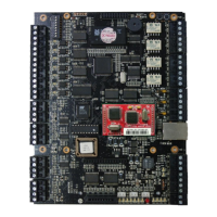
2.2 TCP/IP Module (IIM100)
The user can add an optional TCP/IP module (IIM100) and this module can be used if the user
wants TCP/IP communication to the host PC.
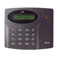
2.3 KEYPAD
The user can connect the optional Keypad to the iTDC main control board and the user can
use the keypad with the LCD display module when the user sets up all functions to the iTDC
manually.