p.32
PRODUCT INSTALLATION
iTDC
2.1 PROCEDURE OF PRODUCT INSTALLATION
Procedure below is fundamental way to install iTDC/iTDC-SR.
(Installer may install with considering with the applicable environment)
1. Set board ID to each of iTDC/iTDC-SR to install.
2. Wiring.
I. Connect iTDC/iTDC-SR to Earth GND for grounding.
II. Wire power.
III. Wire input device depending on number of door control.
IV. Wire output device depending on number of door control.
V. Wire reader depending on number of door control.
VI. Wire communication.
3. Check the status of LED to see weather wiring has been completed well.
4. After checking for test of operating, initialize iTDC/iTDC-SR.
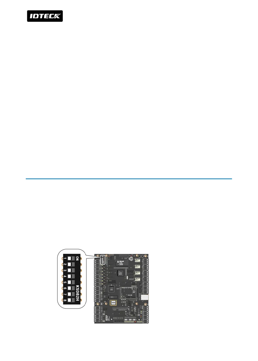
3 BOARD ID (COMMUNICATION ID) SETTING
Board ID is the unique board’s address to communicate with the PC. Each board ID on the
same communication loop must be different.
There is an 8 channel DIP switch on the right upper side of the iTDC board for board ID
setting. Each channel of DIP switch has assigned address values and the board ID is the sum
value of each switch set to “ON” position. Board ID can be set from ‘000’ to ‘255’. Refer to the
example below.