PRODUCT INSTALLATION
iTDC
p.41
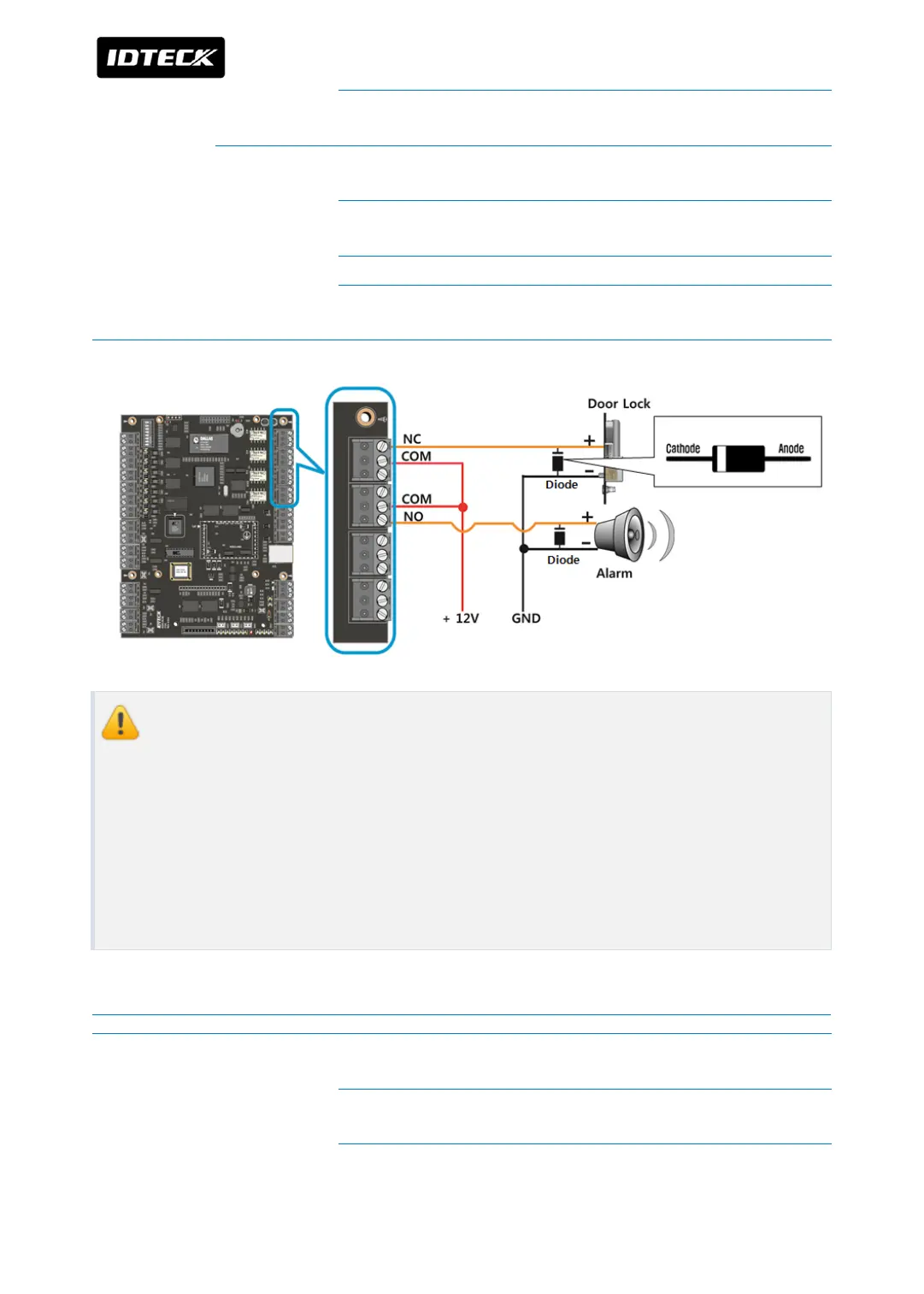
Connect anti-inverse voltage anti-inverse voltage diode between
(+) wire and (-) wire of door lock.
Alarm
Connect +12V wire of DC12V power device to R4COM port of
iTDC/iTDC-SR main board.
Connect (+) wire of alarm to R4NO port of iTDC/iTDC-SR main
board.
Connect (-) wire of alarm to GND (-) wire of power device.
Connect anti-inverse voltage diode between (+) wire and (-) wire
of alarm.
Anti-inverse voltage diode has to be connected near door lock or alarm.
Connect cathode of Diode to + wire of door lock and – wire to anode.
If Anti-inverse voltage diode is not connected, communication error and system
troubles are caused by noise from outside then device’s life is shortened. Also
opposite connection for polarity gives damage to device so please connect it
carefully. The diode is contained in device packing box.
Wiring for door lock, alarm in Power Fail Secure Mode
Door 1 Door Lock
Connect +12V wire of DC12V power device to R1COM port of
iTDC/iTDC-SR main board.
Connect (+) wire of door lock to R1NO port of iTDC/iTDC-SR main
board.
Connect (-) wire of door lock to GND (-) wire of DC12V power