10.4 Interconnecting the Programmer Components for Operation
• Plug the USB end of the Interface Box Cable into the USB port on the side of the
Tablet PC. Plug the other end (fitted with a LEMO
®
-type connector) into the port
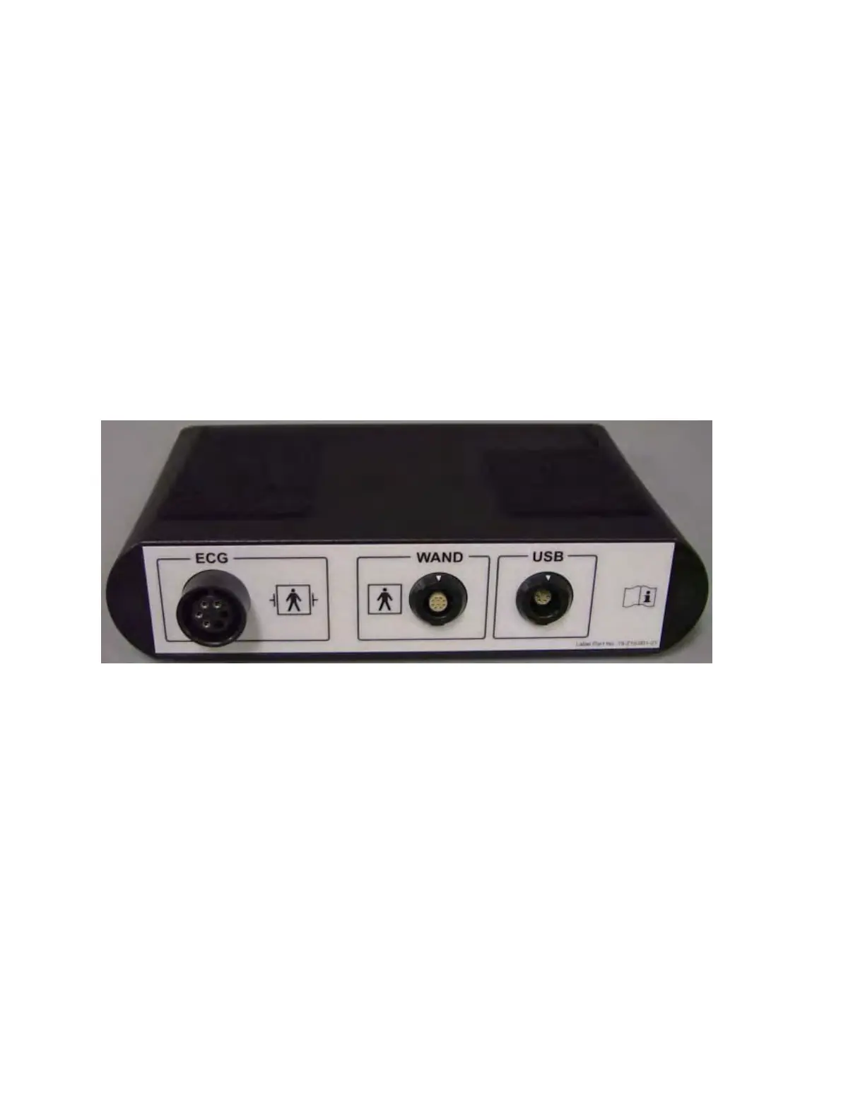
labeled USB on the back panel of the Programmer Interface Box.
• Plug the OMNI II Programmer Wand cable connector into port labeled WAND
on the back panel of the Programmer Interface Box.
Note: If required, the Wand Extension cable may be used to extend the reach of
the Programmer Wand. Connect one end of the Extension cable to the
Programmer Wand cable connector and the other end to the port labeled WAND
on the back panel of the Programmer Interface Box.
• Plug the ECG cable (3-wire with a Type LGH connector) into the port labeled
ECG on the back panel of the Programmer Interface Box.
Warning: Do not attempt to connect any line-powered device (such as a cable-
connection printer) to the OMNI Smart Programmer. This may create an
electrical safety hazard for the patient.
Figure 4: OMNI II Programmer Interface Box
10.5 Programmer Wand
The Programmer Wand has three buttons:
• Interrogate
• Program
• Emergency program with a safe parameter set
The Programmer Wand also has three different sets of indicator lights:
• The Power indicator light, located to the left of the power symbol, is illuminated
when the Programmer Wand is powered.
• The bar graph indicator lights display the strength of the telemetry signal between
the Programmer Wand and the OPTIMIZER Smart IPG.
• The Emergency Programming indicator light, located above the Emergency
Programming button, flashes a few times after Emergency Programming has been
successfully completed.