- 154 -
IS810N-INT Series Servo System User Manual (Brief) Chapter 5 Keypad
Example: Set DI1 and DI2 as the home signals of 2 modules respectively. The corresponding
parameters can be set as follows via background software or the keypad:
H0302 = 131
H0304 = 231
Note: Hardware switch setting can be adopted for the logic of the terminal DI based on an
actual situation.
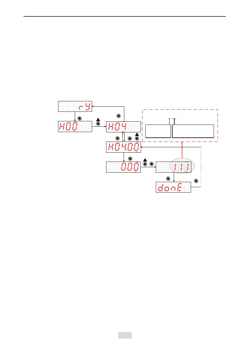
DO Function Setting (When Setting H04-00 Function)
The function number setting of H04 consists of three decimal digits. The rst digit is for the
setting the axis number and the last two digits are for specic terminal functions. Refer to the
red dotted box below:
Figure 5-9 Keypad operation of DI function setting
Function code
group display
Function code
No. display
Parameter
value display
Parameter setting
completed
Servo status
display
Servo ready
MODE
ENTER
1 11
Axis No.
1: Axis 1
Terminal function
11: Fault signal
Shift
MODE
MODE
ENTER
ENTER
MODE
Example: Set DO1 and DO2 as the fault signals of 2 modules respectively. The corresponding
parameters can be set as follows via background software or the keypad.
H0400 = 111
H0402 = 211
Note: The hardware switch setting can be adopted for the logic of the terminal DO based on
the actual situation.
 Loading...