• EX3200, EX3300, EX4200, EX4300 switches except EX4300-48MP and EX4300-48MP-S
switches, EX4500, EX4550, EX6200, or EX8200 switch—Use the Menu and Enter buons
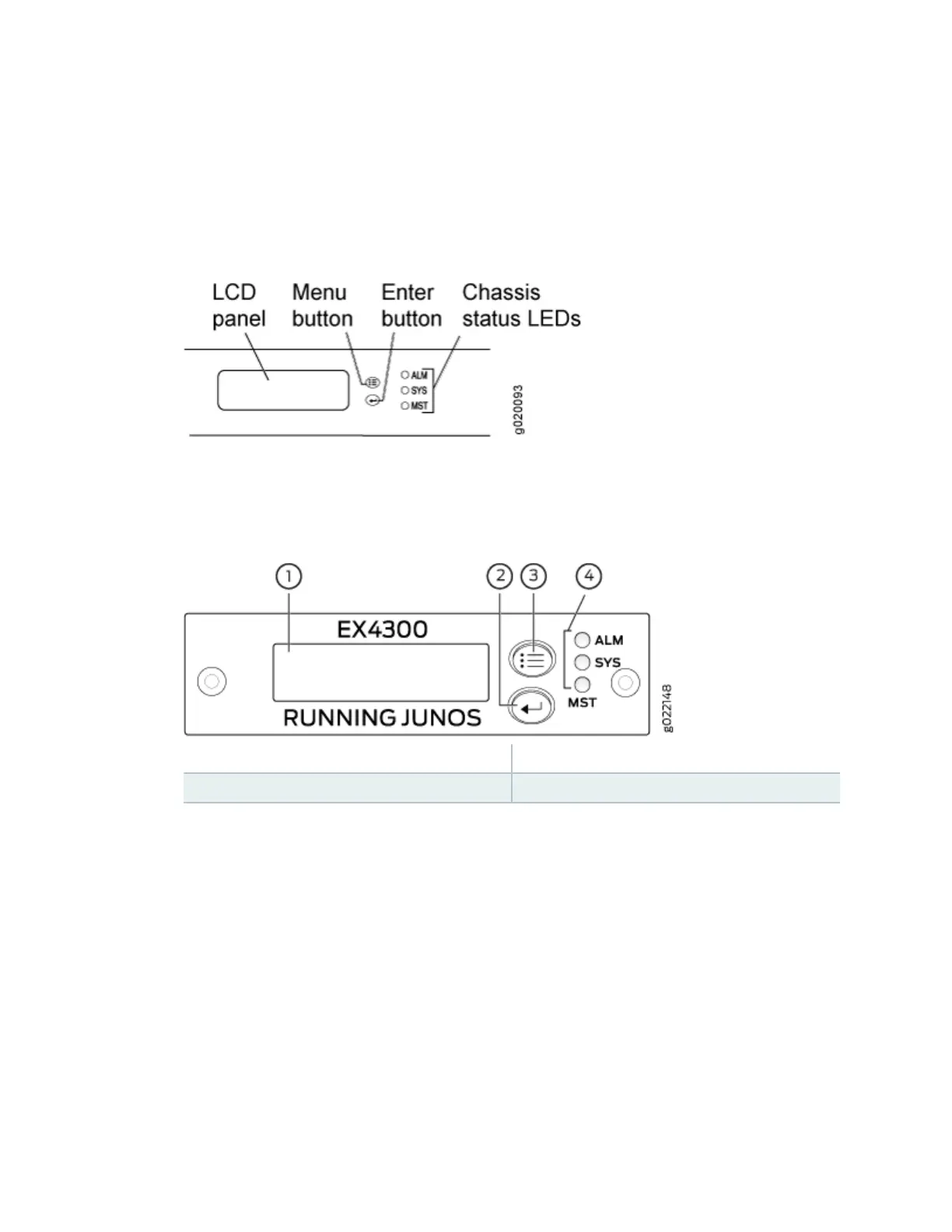
located to the right of the LCD panel (see Figure 83 on page 246 or Figure 84 on page 246):
Figure 83: LCD Panel in an EX3200, EX4200, EX4500, EX4550, or EX8200 Switch
Figure 84: LCD Panel in an EX4300 Switches Except EX4300-48MP and EX4300-48MP-S
Switches
1
— LCD panel 3— LCD panel Menu buon
2— LCD panel Enter buon 4— Chassis status LEDs
a. Press the Menu buon unl you see MAINTENANCE MENU. Then press the Enter buon.
b. Press Menu unl you see ENTER EZSetup. Then press Enter.
If EZSetup does not appear as an opon in the menu, select Factory Default to return the
switch to the factory default conguraon. EZSetup is displayed in the menu of standalone
switches only when a switch is set to the factory default conguraon.
c. Press Enter to conrm setup and connue with EZSetup.
2. Connect the Ethernet cable from the Ethernet port on the PC to the switch.
• EX2200, EX3200, or EX4200 switch—Connect the cable to port 0 (ge-0/0/0) on the front panel
of the switch.
• EX3300 switch—Connect the cable to the port labeled MGMT on the rear panel of the switch.
246