2—
Link acvity LED of the uplink module port
Figure 35: LEDs on the 8-Port 10-Gigabit Ethernet SFP+ Uplink Module for EX4300-32F Switches
1—
Status LED of the uplink module
4—
Status LED the lower port
2—
Link acvity LED of the lower port
5—
Status LED the upper port
3—
Link acvity LED of the upper port
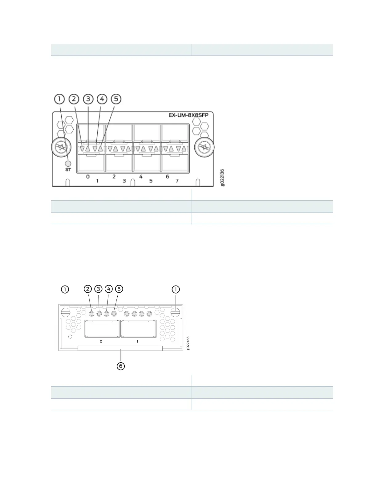
Figure 36: LEDs on the Ports on the 2-Port 40-Gigabit Ethernet QSFP+/100-Gigabit Ethernet QSFP28
Uplink Module for EX4300-48MP and EX4300-48MP-S Switches
1—
Capve screws of the uplink module
4—
Link acvity LED of the uplink module port
2—
Link acvity LED of the uplink module port
5—
Link acvity LED of the uplink module port
3—
Link acvity LED of the uplink module port
6—
Handle of the uplink module
There are four LEDs for each port (labeled 2, 3, 4, and 5 in Figure 36 on page 77). If a port is congured
to operate at 10-Gbps speed by using breakout cables, four 10-Gbps interfaces are created and the four
LEDs for that port becomes operaonal. Each of these LEDs indicates the link acvity on the
77