corresponding interface. If a port is congured to operate at 40-Gbps or 100-Gbps speed, the LED
labeled 2 for that port in Figure 36 on page 77 becomes operaonal and indicates the link acvity on
the corresponding port.
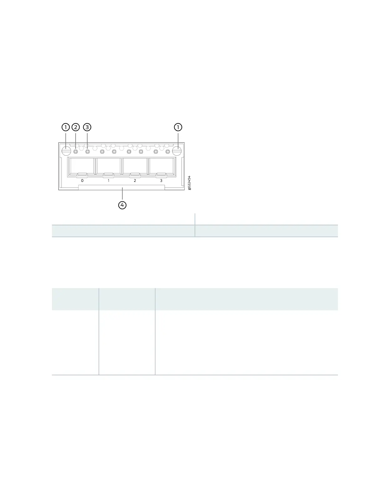
Figure 37: LEDs on the Ports on the 4-Port 1-Gigabit Ethernet SFP/10-Gigabit Ethernet SFP+ Uplink
Module for EX4300-48MP and EX4300-48MP-S Switches
1—
Capve screws of the uplink module
3—
Status LED of the uplink module port
2—
Link acvity LED of the uplink module port
4—
Handle of the uplink module
The Table 21 on page 78 describes the link acvity LED on 10/100/1000BASE-T network ports, SFP
network ports, SFP+ uplink ports, SFP+ uplink module ports, built-in QSFP+ ports, QSFP+ uplink module
ports, and QSFP+/QSFP28 uplink module ports.
Table 21:
Link/Acvity LED
LED Color State and Descripon
Link acvity Green
• Blinking—The port and the link are acve, and there is link acvity.
• On steadily—The port and the link are acve, but there is no link
acvity.
• O—The port is not acve.
On EX4300 switches except EX4300-48MP and EX4300-48MP-S switches, from the Idle menu of the
LCD panel, use the Enter buon on the LCD panel to toggle between the ADM, DPX, SPD, and PoE+
indicators.
Table 22 on page 79 describes the Status LED on 10/100/1000BASE-T Ethernet network ports and
SFP network ports on EX4300 switches except EX4300-48MP and EX4300-48MP-S switches.
78
 Loading...


