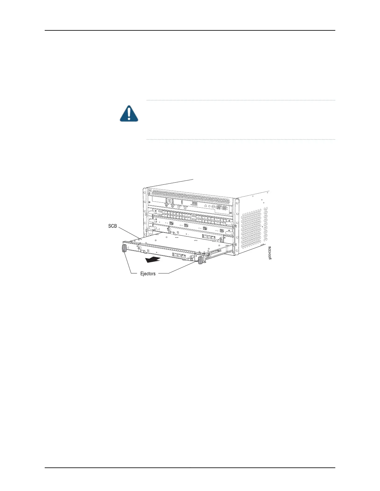
4. Grasp the ejector handles and slide the SCB about halfway out of the chassis.
5. Place one hand underneath the SCB to support it and slide it completely out of the
chassis. Place it on the antistatic mat.
CAUTION: Do not stack hardware components on one another after you
remove them. Place each component on an antistatic mat resting on a
stable, flat surface.
6. Repeat the procedure for the second SCB.
Figure 53: Removing an SCB
Removing the DPCs Before Installing the MX240 Router with a Lift
To remove a DPC (see Figure 54 on page 176):
1. Have ready an antistatic mat for the DPC. Also have ready rubber safety caps for each
DPC using an optical interface on the DPC that you are removing.
2. Attach an electrostatic discharge (ESD) grounding strap to your bare wrist and connect
the strap to an approved site ESD grounding point. See the instructions for your site.
3. Simultaneously turn both the ejector handles counterclockwise to unseat the DPC.
4. Grasp the handles and slide the DPC straight out of the card cage halfway.
5. Place one hand around the front of the DPC and the other hand under it to support it.
Slide the DPC completely out of the chassis, and place it on the antistatic mat or in
the electrostatic bag.
175Copyright © 2017, Juniper Networks, Inc.
Chapter 16: Installing the MX240 Router