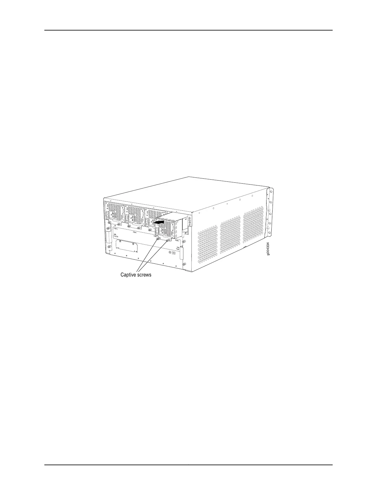
4. Tighten both captive screws at the bottom of the power supply.
5. Attach the power cord to the power supply.
6. Attach the power cord to the AC power source, and switch on the dedicated customer
site circuit breaker. Follow the instructions for your site.
7. Move the AC input switch next to the appliance inlet on the power supply to the on
(|) position and observe the status LEDs on the power supply faceplate. If the power
supply is correctly installed and functioning normally, the AC OK and DC OK LEDs light
steadily, and the PS FAIL LED is not lit.
Figure 104: Installing an AC Power Supply
Related
Documentation
MX240 AC Power Supply Description on page 90•
• Removing an MX240 AC Normal-Capacity Power Supply on page 335
• Preventing Electrostatic Discharge Damage to an MX240 Router on page 444
• AC Power Supply Electrical Specifications for the MX240 Router on page 127
257Copyright © 2017, Juniper Networks, Inc.
Chapter 21: Installing Components