Docu-No.: 1090020601-EN Rev. 1.2.1 Page 119
Appendix 12
KCM wiring examples 12.4
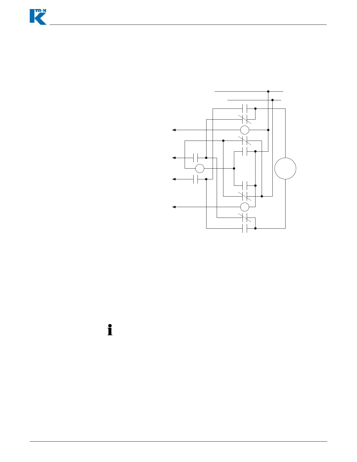
12.4.19 Hi/Lo Auto gear external switching circuit
The following diagram shows how to safely wire the KCM for
automatic gear switching functions for the LWF/LWB application when
a K2M feeder with dual speed gearbox is used.
Set-up is as follows:
Program correct gear reductions in MACHINE menu
Program MDU Relay 1 function as Hi/Lo Gear, polarity - normal
Program MDU Relay 2 function as Hi/Lo Gear, polarity - inverse
Connect KCM DC drive inputs as shown in Fig. 12.9
Test function and re-connect DC motor wiring if screw speed
changes are reversed.
Fig. 12.19HiLo gear selection wiring
M
Drive
DC+
Drive
DC-
CR1
CR2
CR3
High
Gear
Low
Gear
L1
N
+
-
• CR1-CR3 are independent AC contactors with 15 A contacts