4Installation
4.11I-O wiring connections
Page 46 Docu-No.: 1090020601-EN Rev. 1.2.1
4.11 I-O wiring connections
Notes:
• The <F> symbol shows the field side of the diagram. Internal
circuits are shown to aid understanding of function.
• Sections 4.11.1 to 4.11.7 define I-O for drive cards in various
configurations with sections 4.11.1 to 4.11.4 describing I-O
common to all drives.
• Sections 4.11.8 to 4.11.12 define I-O from the KCM CPU circuit
card.
4.11.1 Safety input wiring to KCM Drive - J1
4.11.2 Drive enable input to KCM Drive - J1
Fig. 4.7 Safety switch wiring-Drive
Notes:
• The maximum voltage drop across the contacts is 2.0 Vdc.
• Safety input wiring is made at terminal strip J1 on the drive pcb.
• The Safety Input must be at 24 Vdc to engage the safety relay and
permit KCM drive output.
• Failure of this input will cause <#15 MDU_SRelay> alarm.
Safety
Switch
In
24 Vdc
Drive – J1
1
2
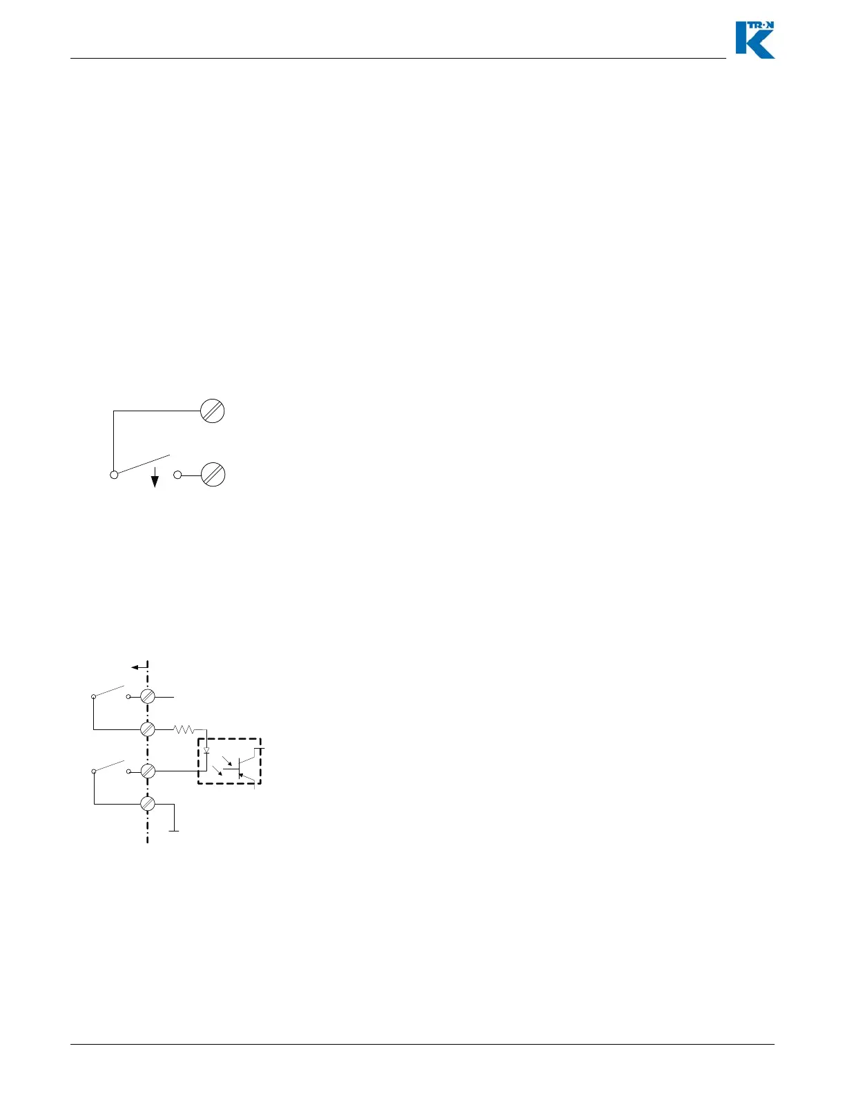
Fig. 4.8 Drive enable wiring-Drive
Notes:
• The maximum voltage drop across the contacts is 2.0 Vdc.
• The Drive Enable Input must be at 24 Vdc to permit KCM drive
output.
• The input signal as shown in optically isolated from the KCM.
• Drive enable input wiring is made at terminal strip J1 on the drive
pcb.
1k
Drive Enable +
Drive Enable -
+24
Vdc
Com
Close to
Run
Close to
Run
F
Drive – J1
3
4
5
6