4Installation
4.11I-O wiring connections
Page 50 Docu-No.: 1090020601-EN Rev. 1.2.1
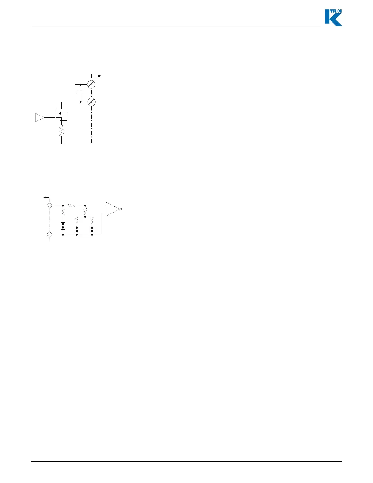
4.11.10 KCM CPU analog output - J9
4.11.11 KCM CPU analog input - J9
Notes:
• JP2 = 0-10 Vdc
• JP3 = 0-5 Vdc
• JP4 = 0-20 mA
– Input (+) = J9-5
– Input (-) = J9-6
• 0-20mA/4-20mA with 100
impedance
• 0-5 Vdc with 94.5 k
impedance
• 0-10 Vdc with 65.3 k
impedance
This circuit shows the analog output (0-20mA/4-20mA) that is
available from the CPU pcb at terminal J9.
The output function is programmed via the I-O menu, Analog Output
sub-menu.
• I Output (+) = J9-3
• I Output (-) = J9-4
Fig. 4.16 CPU analog output circuit
Analog Out (+)
F
Com
Analog Out (-)
+12Vdc
49.9
CPU-J9
J9-3
J9-4
This circuit shows the selectable range analog input that is available
at the CPU pcb at terminal J9.
The input function is programmed via the I-O menu, Setpoint Input
sub-menu as parameter <SOURCE> = <CPU Analog>.
Use only one jumper at the required location for the voltage or current
input used.
Fig. 4.17 CPU analog input circuit
Analog In+
F
Analog In-
J9-5
J9-6
CPU-J9
16.2k
118
475
4.53k14.0k
JP4
JP3 JP2
0-20mA 0-5Vdc 0-10Vdc
+
-