Docu-No.: 1090020601-EN Rev. 1.2.1 Page 49
Installation 4
I-O wiring connections 4.11
4.11.8 KCM CPU digital outputs - J8
4.11.9 KCM CPU digital inputs - J8
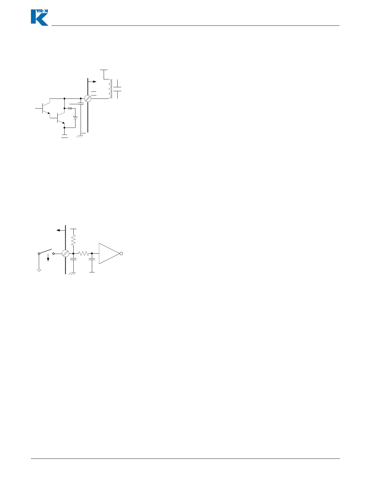
Fig. 4.14 CPU digital output example
This is an example of one of four programmable digital outputs
available from the KCM CPU pc board. This example is driving a
relay-CR.
Notes:
• Four programmable outputs are available.
• Functions are programmed as <CPUout1, CPUout2, CPUout3,
CPUout4>.
• A “low” output (sinking) condition = “true”.
• Maximum value of Vx = 40 Vdc. Maximum sink current = 100 mA
• Connections are made at the CPU pcb, terminal strip J8.
– CPUout1 = J8-6
– CPUout2 = J8-7
– CPUout3 = J8-8
– CPUout4 = J8-9
Dig
Out
4.7nF
Vx
PE
Com
F
CR
CPUout1=J8-6
CPUout2=J8-7
CPUout3=J8-8
CPUout4=J8-9
J8
Fig. 4.15 CPU digital input example
This is an example of one of the four programmable digital inputs on
the KCM CPU circuit card.
Notes:
• Maximum current from terminal 3, +24 Vdc, all connections, is 350
ma.
• A low input provides an ‘ON’ condition with <Normal> polarity.
• Connections are made at the CPU pcb, terminal strip J8.
• Vin maximum = 24 Vdc
• Functions are programmed as <CPUin1, CPUin2, CPUin3,
CPUin4>.
– CPUin1 = J8-1
– CPUin2 = J8-2
– CPUin3 = J8-3
– CPUin4 = J8-4
+5Vdc
4.75k
10k
4.7nF
100nF
Dig
In
PE
Com
F
CPUin1=J8-1
CPUin2=J8-2
CPUin3=J8-3
CPUin4=J8-4