Docu-No.: 1090020601-EN Rev. 1.2.1 Page 121
Appendix 12
KCM wiring examples 12.4
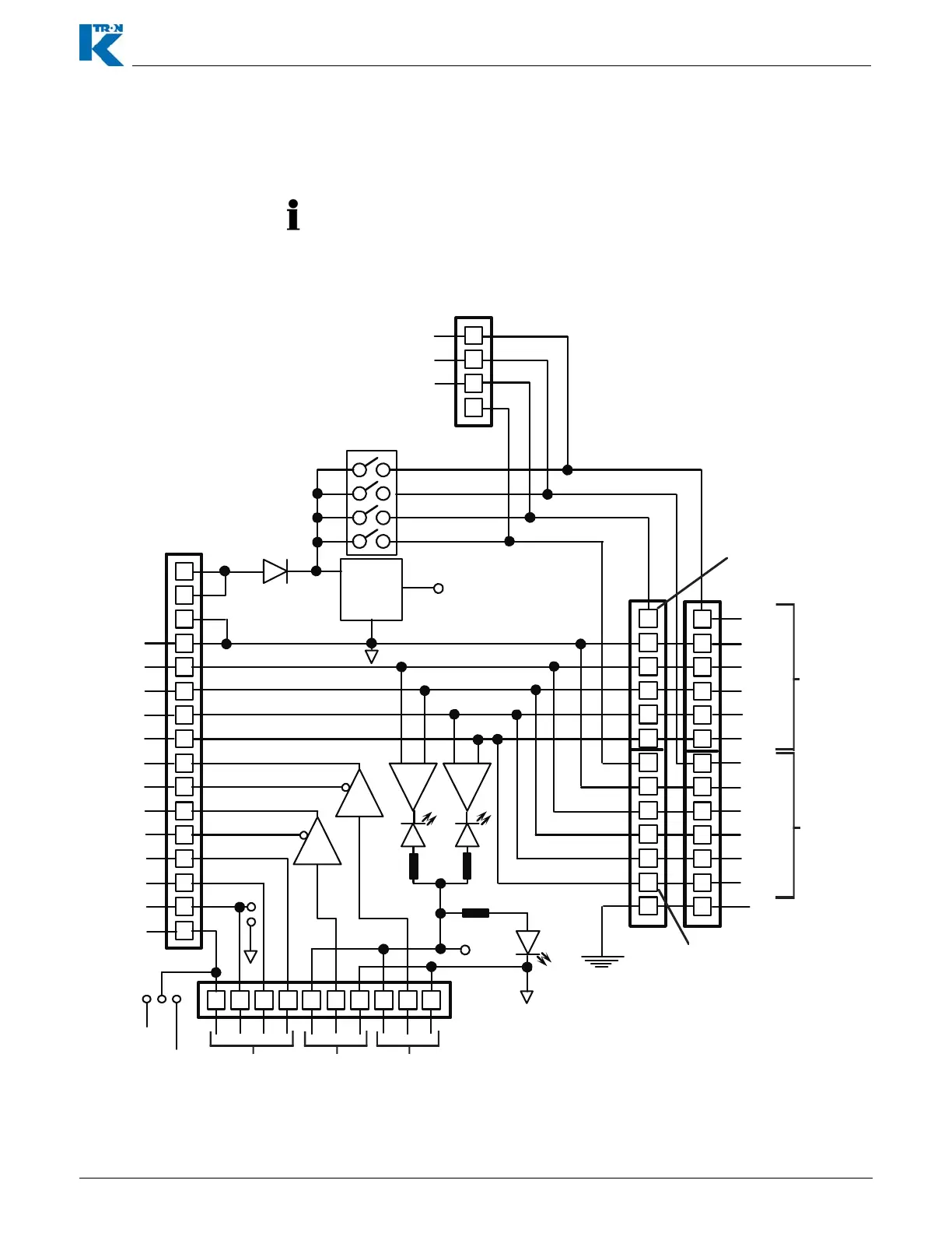
12.4.22 Schematic of SIB board-9191601650
The Scale Interface pc board-SIB is used when the KCM is mounted
away from the feeder.
• Do not connect SFT power to LK-5
• Turn the DIP switch to <On> for all active SFT positions.
Fig. 12.22SIB schematic
.
43
44
45
46
47
48
49
50
51
52
53
54
1
2
3
4
5
6
1
2
3
4
5
6
GRD
1
2
3
4
5
6
1
2
3
4
5
6
GRD
S1
S2
S3
S4
Vreg
+5 V dc
28
+5 Vdc
COM
Tx-
Tx+
Rx-
Rx +
Tx Rx
Yel
Red
SpeedSlip
GRD
+5 Vdc
+12 Vdc
JU-1
JU-2
Com
SFT Tx-
SFT Tx+
SFT Rx-
SFT Rx+
Spd +
Spd -
Slip +
Slip -
-
Aux 1
Aux 2
Aux 3
Aux 4
To Controller
LK-4
SFT Disable Sw
Com
Tx-
Tx+
Rx-
Rx +
SFT Cable Shields
SFT #4
LK-2
LK-1
SFT#3
LK-3
Motor Speed
Belt Slip
Auxiliary
26LS31
U1
U2
26LS33
-+
-+
SFT #1
SFT #2
SFT #3
SFT #4
+11.3
Vdc
Com
Tx-
Tx+
Rx-
Rx +
+11.3
Vdc
41
41
42
42
1
2
3
4
+12 Vdc #1
+12 Vdc #2
+12 Vdc #3
LK-5
Note: if LK-5 is used, all poles of the DIP Switch must be open
SFT#1
SFT#2
Yel
27 26 25 23 24 21 23 22 212