Docu-No.: 1090020601-EN Rev. 1.2.1 Page 101
Appendix 12
KCM wiring examples 12.4
12.4 KCM wiring examples
12.4.1 System wiring examples
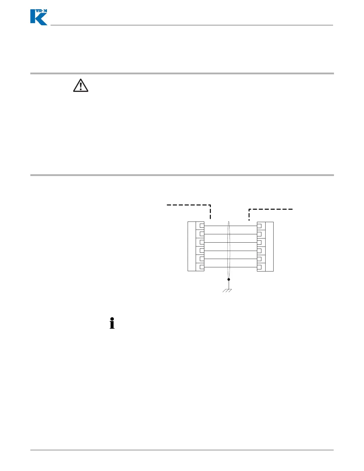
12.4.2 KCM to KSU-II wiring at K-Port 1/2
▲ The 450 watt DC motor drive and the 1600 watt DC motor drive are
wired in a similar manner but will be shown independently.
▲ As for all applications, refer to the wiring diagrams supplied for
your project as the official source for wiring your system.
▲ These wiring diagrams are provided as basic information only.
Your system may be wired differently. Please be careful!
▲ SIB means scale interface circuit board mounted at the machine
for speed signal interfacing.
▲ Line voltage input is 115/230 Vac single phase, 50/60 Hz.
▲ Wire colors, if shown, may change for your application. Refer to
your provided electrical diagrams for specific colors.
Fig. 12.1 KCM to KSU-II wiring example
• If the KSU-II is more than 10 meters from the KCM, KSU-II power
must be supplied from an independent power supply.
• Either K-Port #1 or #2 may be used.
• Only one KSU-II may be powered from a single KCM.
KCM
K-Port 1 / 2
123456
KSU II Primary Port
J14 / J15
COM
Rx+
Tx+
Rx-
Tx-
Vcc
123456
JP2
123456