Docu-No.: 1090020601-EN Rev. 1.2.1 Page 91
Optional Devices 11
Host communication circuit cards 11.1
11 Optional Devices
Options that can modify or extend the KCM’s performance are defined
here. Host communication circuit cards are described in manuals that
are identified in this section.
11.1 Host communication circuit cards
These circuit cards plug into the Host slot on the KCM CPU circuit
card. The host port is configured via the KSU-II SYSTEM menu or via
the PC connected to the Config port on the KCM.
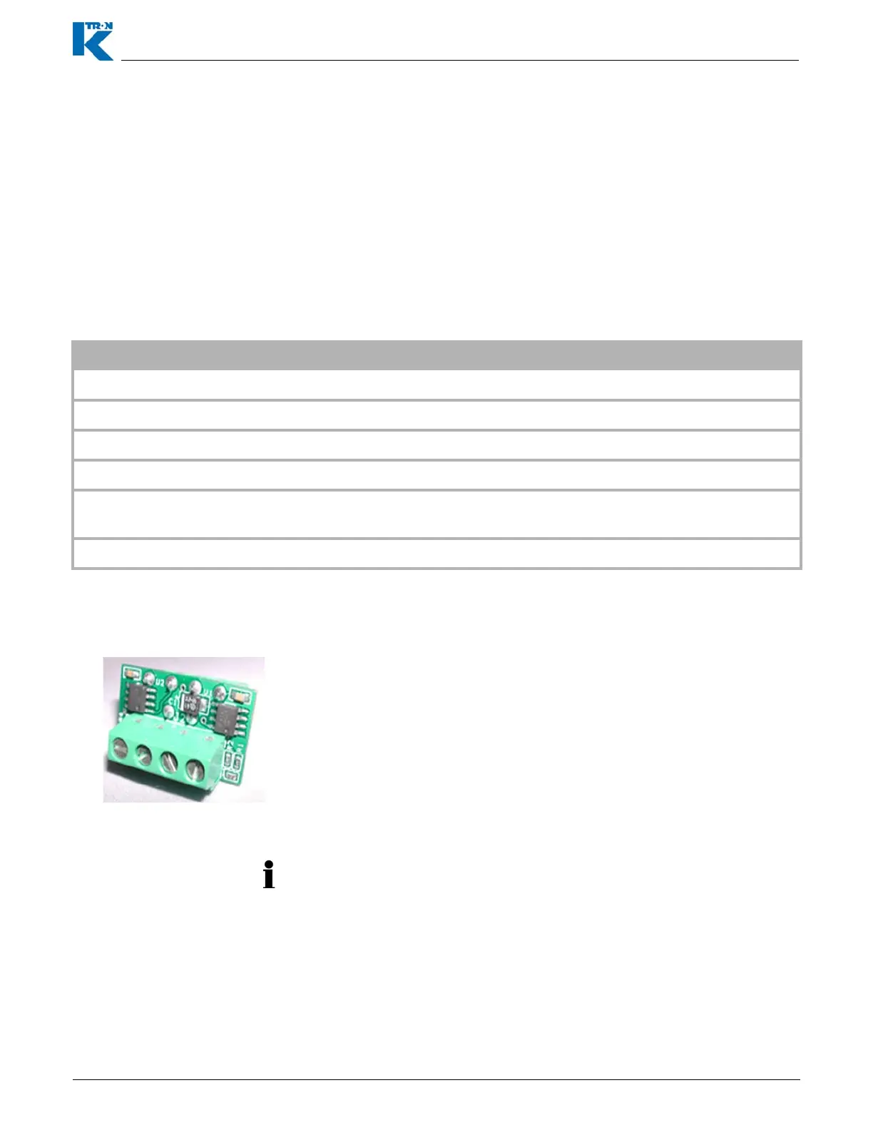
11.2 Encoder interface circuit card
Protocol Part Number Document Number
DeviceNet 0000005105 0590020609
ProfibusDP 0000005108 0590020607
Modbus Plus 0000005107 0590020608
Ethernet/IP or EthernetTCP 0000005106 0590020610
Modbus RTU or AB DF1 0000001737 Use this document - see K-Port Comm
Board.
Profinet 0000023130 1190020601
Differential speed signals that come from the Scale Interface pcb are
converted to single ended inputs for the KCM drive boards by the use
of the Differential Receiver-Encoder Interface pcb. (Fig. 11.1)
• Differential receiver pcb (0000006384) must be installed onto J2 on
the drive circuit card when the Scale Interface pcb interfaces to the
KCM. (Fig. 12.11)
• For a single differential speed input from the scale interface pcb,
bring into <SPD1 +/-> and select <Single input> for the tachometer
selection as shown in Fig. 12.12.
Fig. 11.1 Encoder interface photo
• The 0000006384 encoder interface functions with all drives except
the AC interface drive.