2 Assembly and Function
2.3 Structure
Page 20 Docu-No.: 1090020601-EN Rev. 1.2.1
2.3.2 Circuit assemblies
The KCM CPU pc board is mounted to the rear of the front swing-out
cover. The drive pc board with KCM power supply is mounted to the
bottom heatsink plate of the housing. (Fig. 2.3)
There are two choices for the on-board KCM operational display. First,
a fully functional display and keypad assembly may be mounted to the
rear of the KCM cpu pc board and permit access via the front of the
cover for all operational actions. (Fig. 2.1) The second choice provides
only the four status LEDs that indicate machine running and alarm.
(Fig. 2.2) The first case permits operation of the KCM without any
other external components and is suited for simple machine mount
installations where operator interaction is required at the controller.
The second case requires the addition of one or more of the following:
KSU-II, KSC, K-Vision or KSL user interface. The choice depends
upon application. If communications to a host computer or PLC is
required, a Host Communications pc board is mounted to the KCM
CPU pc board. Also connected to the KCM CPU is the K-PROM
memory module that contains all parameter and KGR file data.
Lastly, if the speed signal is differential, a plug-in circuit card permits
the receipt of this signal where normally a single ended input is
received.
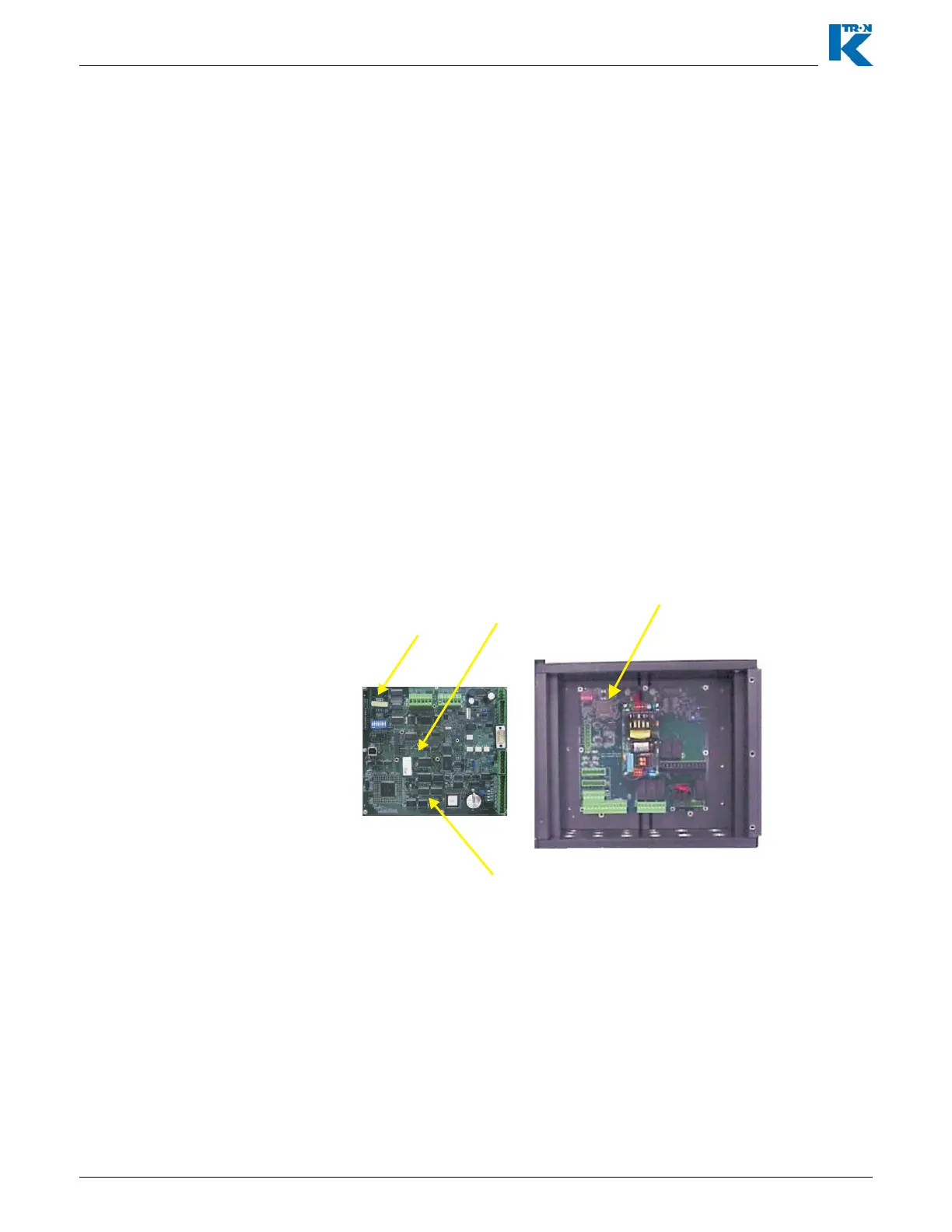
KCM element identification
(1) CPU circuit card
(2) Drive circuit card
(3) Host comm. circuit card
(4) K-PROM circuit card
Fig. 2.3 KCM open