10 Troubleshooting
10.2KCM CPU LEDs
Page 82 Docu-No.: 1090020601-EN Rev. 1.2.1
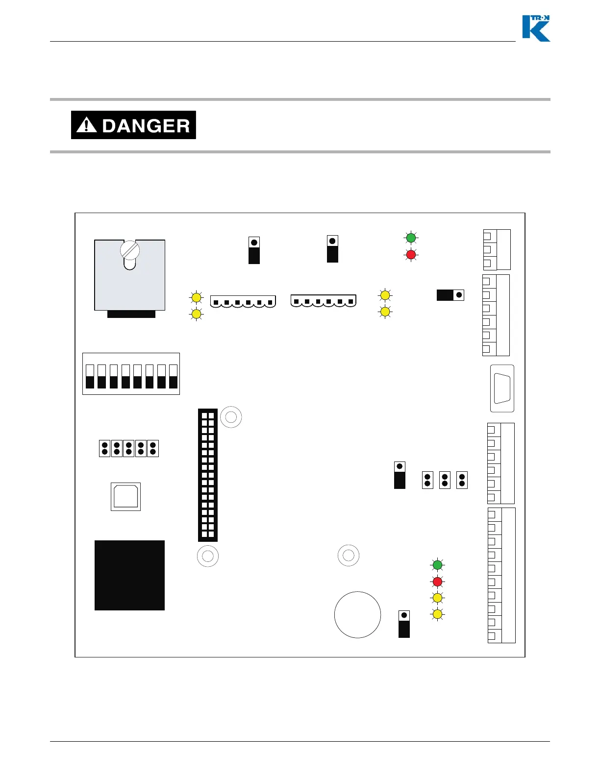
10.2 KCM CPU LEDs
Use the internal LEDs to evaluate KCM function. A listing is provided
to help diagnose problems.
▲ It is dangerous to open the KCM cover without removing power as
high voltage is present on the Drive printed circuit board.
Fig. 10.1 KCM CPU LED locations
J10
J8
1
2
3
4
5
6
7
8
9
10
1
2
3
4
5
6
1
2
3
4
5
6
1
2
3
J9
J11
JP4 JP3 JP2
1
0-20ma
Analog In Select
0-5V
1
0-10V
1
JP1
1
Reset
Run
JP5
1
4-Wire
2-Wire
BootLoad Port
1
2
9
10
K-Prom
Memory
Installed
CPU
68340
1
2
33
J3
1 2 3 4 5 6 7 8
ON
SW1
OPEN
OFF
Alive
TxD
RxD
Alarm
Alive
Error
COMMUNICATION/HOST BOARD
DB-9
Config-
P1
1
Pwr
GND
TxD+
TxD-
RxD +
RxD -
1
Pwr
GND
TxD+
TxD-
RxD +
RxD-
TxD2
RxD 2
TxD1
RxD1
K-Port 1
K-Port 2
1
2-wire
4-wire
JP7
1
2-wire
4-wire
JP6
JP8
1
+
CR2032
J13