Docu-No.: 1090020601-EN Rev. 1.2.1 Page 67
KCM Set-Up 5
GWB Application drive set-up 5.7
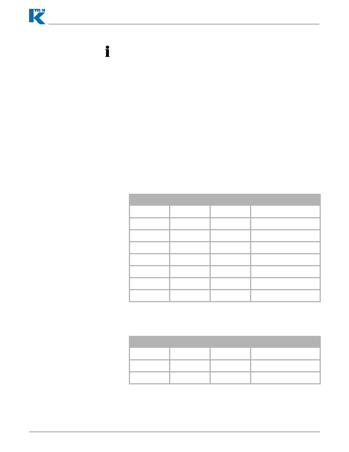
5.7.2 Setup DC Drive Boards
Both of these DC motor drive boards have a 6 position DIP switch to
set the address. The address is based on switches 3, 4, and 5. as
shown below.
5.7.3 Setup Vibrator Drive Boards
The Vib. Drive board has a four position DIP switch. The addresses
are based on switches 1, 2, 3 as shown below.
• The KCM stepper and the AC interface boards can only have
address 1 to 4 so no it is not possible to use these units for feeder
5 .. 8
• Addressing the Motor Drive Boards using their DIP switches.
• When using the KCM GWB with several motor drive boards (MDU),
it is critical to address the MDU boards. It is important to have the
motor drives start with address 0,0,0. There are eight ingredient
feeders possible with the GWB, and the motor drive boards have
addresses selected by three or two dip switches. The board
addresses based on the switches range from 0 .. 7, and represent
ingredient feeder numbers of 1..8. It is important to start with
ingredient 1 and go up from their without skipping. In other words, if
there are three ingredients to be a GWB system, the drive boards
should have 0,0,0, then 0,0,1 then 0,1,0 as the board
SW3 SW4 SW5 Ingredient Address
0001
0012
0103
0114
1005
1016
1107
1118
SW1 SW2 SW3 Ingredient Address
0001
0012
0103