5 KCM Set-Up
5.1 Initial set-up for KCM CPU
Page 58 Docu-No.: 1090020601-EN Rev. 1.2.1
5.1.5 K-PROM configuration
5.1.6 Display backlight control
The KCM-GD 3.5 inch LCD display has auto dimming to prolong the
life of the display module. If no operator activity occurs for many
hours, the display will auto dim.
Hitting any key will bring the display back to full brightness.
5.1.7 Setting display brightness
Press ESC and 7 to decrease, ESC and 9 to increase the display
brightness manually.
The K-PROM stores the actual data only on power shutdown not on
CPU reset.
The K-PROM must be installed on the KCM CPU pc board and it will
be loaded by the Config port connection for communications or via the
user interface for operations. The K-PROM can be moved from a
failed KCM to a replacement KCM as the parameter and
communication data are stored therein. This exchange eliminates the
need for controller re-programming.
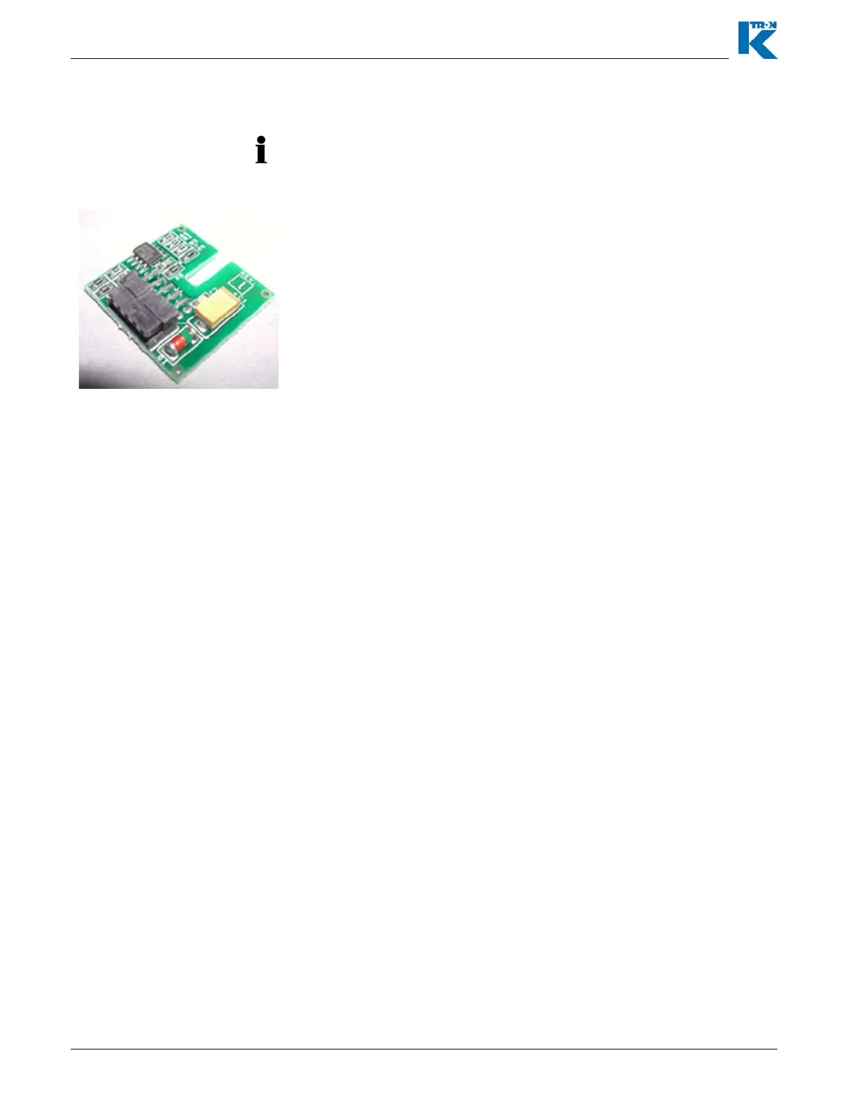
The K-PROM is installed upside down on the KCM CPU circuit card in
the location marked “K-PROM card”. It is secured by an M3 screw.
Fig. 5.1 K-PROM