Docu-No.: 1090020601-EN Rev. 1.2.1 Page 47
Installation 4
I-O wiring connections 4.11
4.11.3 Digital input #1 and #2 at Drive pc board
4.11.4 Drive output relays K1-K3 - J5
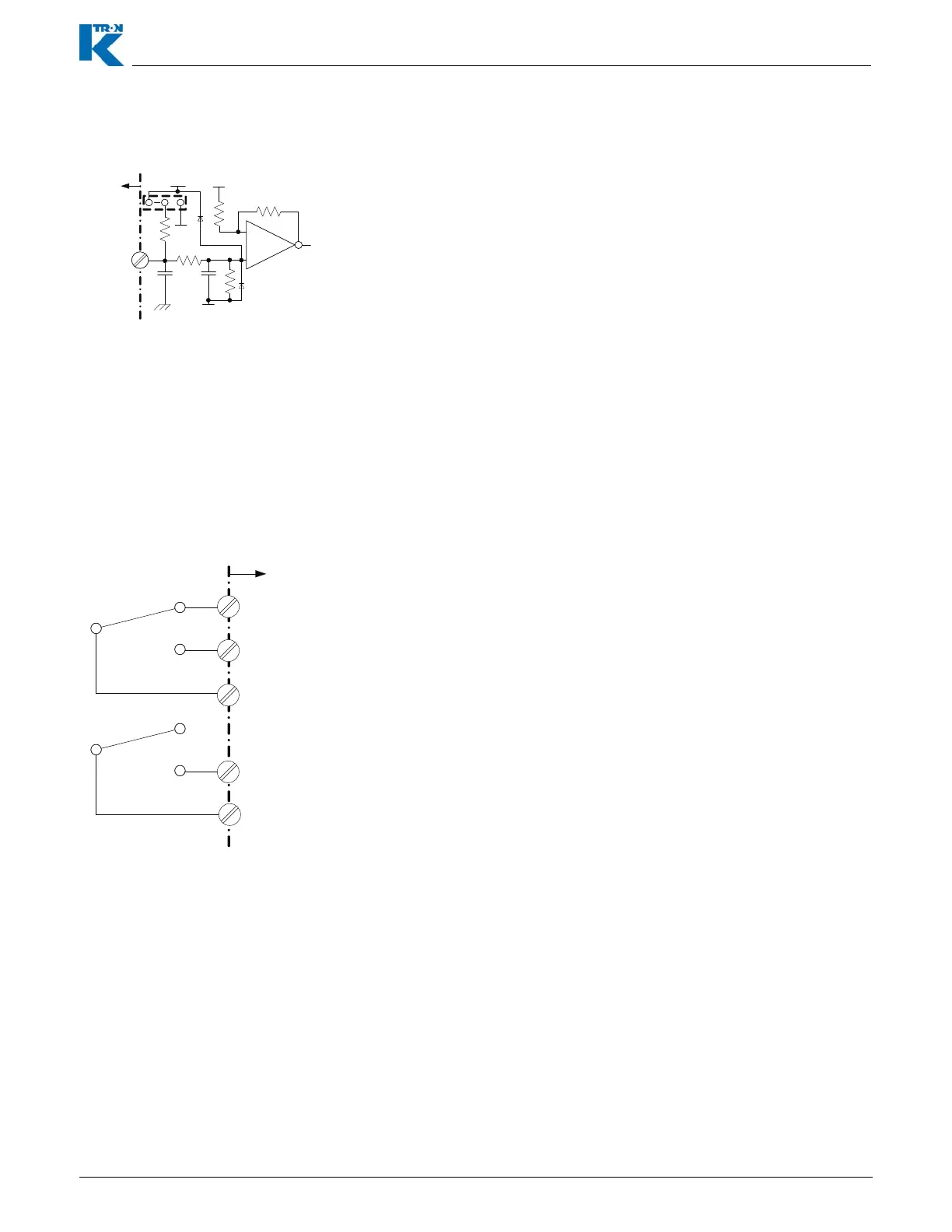
Fig. 4.9 Digital input example-Drive
Notes:
• These two digital inputs are found on the Drive pcb at terminal J1.
• These two inputs on the drive circuit board have the possibility to be
wired for either pull-up or pull down applications. Both digital inputs
are programmable in function.
• If the jumper is connected to +24 Vdc, the input must be taken to
common to function. If the jumper is connected to common, the
input must be taken to at least +5 Vdc to operate.
• A low input provides an ‘ON’ condition with <Normal> polarity.
• Function is programmed as <MDUin1> or <MDUin2>.
• Drive digital input wiring is made at terminal strip J1 on the drive
pcb.
– MDUin1 = J1-8
– MDUin2 = J1-11
Input 1 & 2
PE
24 Vdc
5Vdc
+
-
Com
Com
F
J1-8(1)
J1-11(2)
K1-K2 drive board relay wiring.
Notes:
• Relay 1 and Relay 2 are SPDT types, while Relay #3 is a SPST
type.
• Relay function is programmable via the user interface.
• Function is programmed as <MDUrel1, MDUrel2, MDUrel3>.
– MDUrel1 = relay K1, MDUrel2 = relay K2, MDUrel3 = relay K3
• Relay wiring is made at the drive pcb, terminal strip J5.
– K1-NC = J5-3, K1-NO = J5-2, K1-COM = J5-1
– K2-NC = J5-6, K2-NO = J5-5, K2-COM = J5-4
Fig. 4.10 Drive relays K1-K3
N. C.
N.O.
COM
K1,K2
Relay
Contacts
J5-3(K1)
J5-6(K2)
J5-2(K1)
J5-5(K2)
J5-1(K 1)
J5-4(K 2)
F
N.O.
COM
K3 Relay
Contacts
J5-8
J5-7