Docu-No.: 1090020601-EN Rev. 1.2.1 Page 57
KCM Set-Up 5
Initial set-up for KCM CPU 5.1
5.1.2 KCM CPU DIP switch setting
Positions 1-5 set the address of the KCM on the K-Net. Positions 6-8
control the function of the K-Port channel #1.
5.1.3 KCM addressing with CPU DIP switch positions 1-5
Note:
• The address of <00000> as set above is a special case. If the switch
is set to <00000>, the KCM address is set under software control
via the user interface.
5.1.4 K-Port 1 function via KCM CPU DIP switch positions 6-8
▲ Off = <0>, On = <1> for each switch position
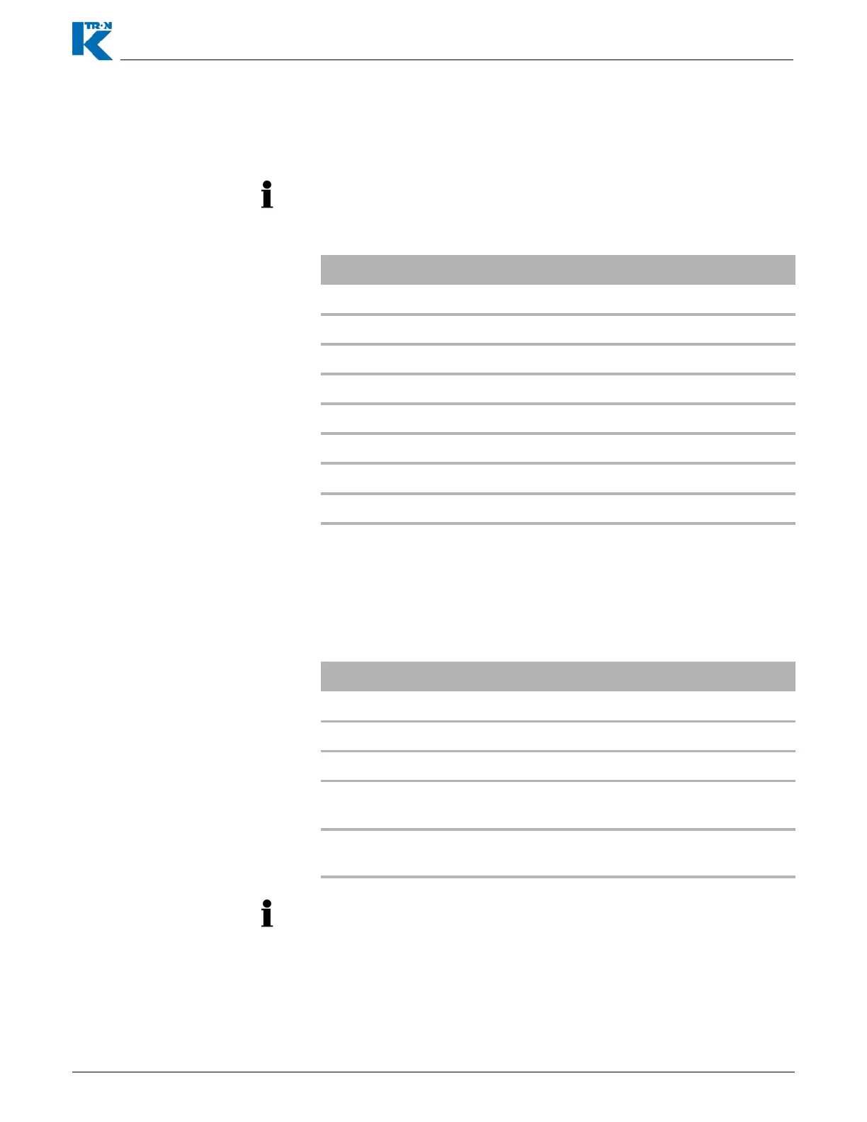
Address SW1 SW2 SW3 SW4 SW5
0 Off Off Off Off Off
1OnOffOffOffOff
2 Off On Off Off Off
3 OnOnOffOffOff
4 Off Off On Off Off
5 On Off On Off Off
......
31 On On On On On
K-Port #1 Function SW6 SW7 SW8
Software controlled Off Off Off
Set for KSU-II use On Off Off
Set for KSL use Off On Off
Set for KMB, 19.2 kbaud (K-
Vision, KSC or PC Tool) use
On On Off
Set for KMB, 38.4 kbaud (KSC
or PC Tool) use
Off Off On
When Dip Switch 6-8 are ON for more than 2 seconds (under power),
the config port is set to User IF.