4Installation
4.10Drive connection summary
Page 40 Docu-No.: 1090020601-EN Rev. 1.2.1
4.10.6 DC motor drive power - J6.
4.10.7 DC motor drive feedback - J2
Note:
• If a SFT Interface board is mounted to the feeder and where the
KCM is remotely mounted for DC motor applications, a small circuit
card (0000006384) with a differential line receiver is plugged into J2
to receive the single differential speed signal from the feeder. The
speed signal is connected to this circuit card.
4.10.8 Change DC motor shaft rotation
To change the shaft rotation, switch the polarity of the motor armature
leads either at the KCM DC Drive or at the motor. Do this only with
power removed from the KCM.
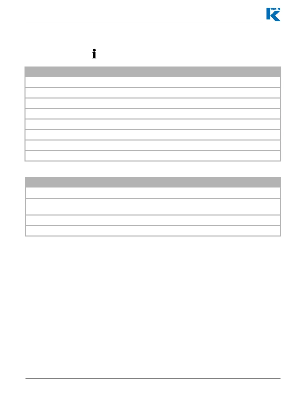
Connections for both the 450 and 1600 watt dc motor drives.
Terminal Function Notes
J6-1 Motor Power (-) DC motor voltage (-)
J6-2 Motor Power (+) DC motor voltage (+)
J6-3 PE/GRD Earth/ground
J6-4 PE/GRD Earth/ground
J6-5 PE/GRD Earth/ground
J6-6 Neutral Neutral leg of a 115 Vac line or 230 Vac
J6-7 L2 Second leg of a 230 Vac line
J6-8 L1 Line input (hot) either 115 Vac or 230 Vac
Terminal Function Notes
J2-1 + 5 Vdc + 5 Vdc power at 100 mA for sensor power
J2-2
Frequency In A
Input channel A from speed sensor. Also used if the sensor has
only a single output.
J2-3 Frequency In B Input channel B from a quadrature velocity sensor.
J2-4 Common Common for sensor