4.5 Braking transistor
Braking transistor handling
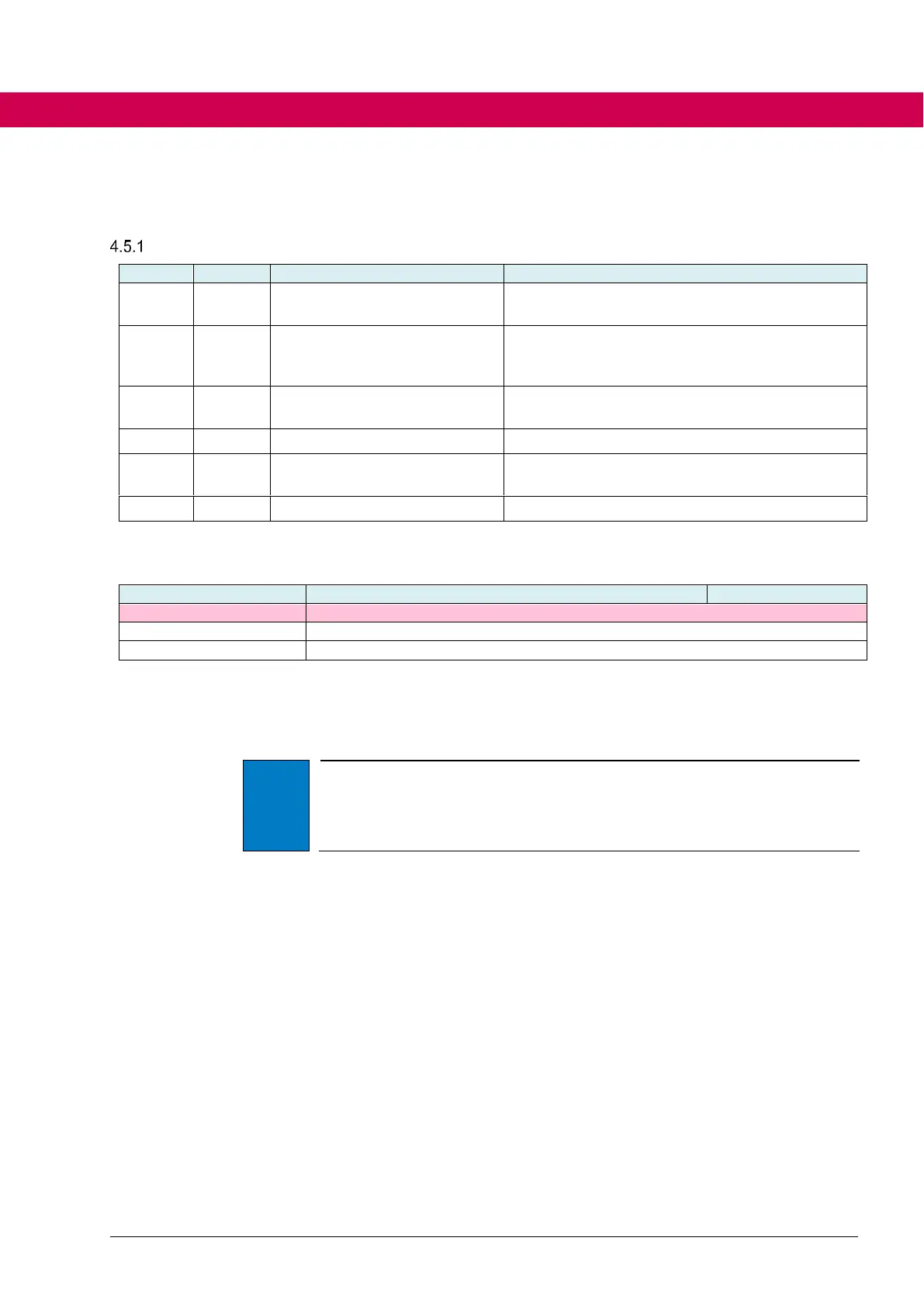
enable braking trans. source
Defines a digital input to activate the braking tran-
sistor
Threshold of the DC link voltage to activate the
braking transistor. (is internally limited by the input
voltage) resolution: 0.1V
Measured DC link voltage at the end of the pre-
charging
braking transistor function
Activation of the braking transistor functionality
braking transistor default level
Display of the default switch-on threshold of the
braking transistor (depending on the power unit)
Braking transistor activation / deactivation options
Parameter de36 indicates if the used inverter contains a braking transistor module.
braking transistor default level
the inverter does not contain a braking transistor
Default switch-on threshold in 0.1V resolution
On default set loading the value for pn32 braking transistor level is written to the
value of de36. The braking transistor is not activated automatically.
By way that the braking transistor can be used, the braking transistor function must
generally be enabled with is30 braking transistor function.
If parameter is30 braking transistor function is not set to 1: on, the braking
transistor is never switched on by the software, regardless of all other parame-
ters.
Parameter is30 is already activated at the factory for devices with sub-
mounted braking resistor.
4.5.1.1 Braking transistor activation / deactivation
4.5.1.1.1 Voltage-dependent activation
The response threshold of the braking transistor is set in parameter pn32 braking
transistor level with a resolution of 0.1V.
When connecting the mains the DC link of the inverter is precharged to the max.
value of the input voltage (U
DC link
≈ √2 * U
mains
). This DC link voltage value at the
end of the precharging limits internally the switching level of the braking transistor.
The value can be read in ru63 Uic voltage at Power On. If the value in pn32 < 1.06
* ru63, the switching level of the braking transistor is internally set to 1.06 * ru63.
This threshold ensures that the braking transistor is not responded by the mains
input voltage. However, provided that the mains input voltage does not increase
upon completion of the precharging of the DC link.
The default values for the braking transistor threshold are depending on the volt-
age class of the inverter.

 Loading...


