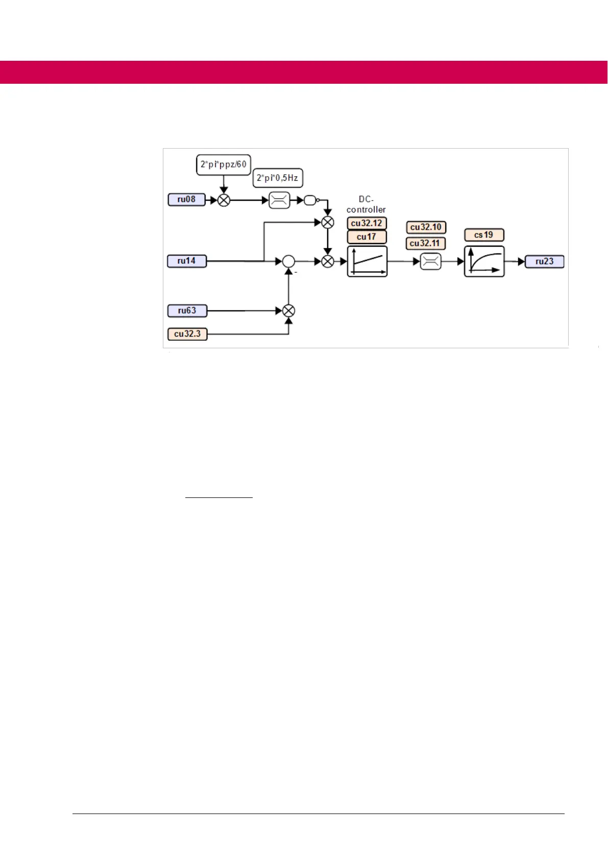
Figure 23: Circuit diagram of the DC control (ppz=number of pole pairs)
4.4.22.7.1 Design of the DC link voltage controller
The DC link voltage controller is designed according to the symmetrical optimum.
Tdelay = 1.125ms , e.g. Td = 4*TpBase (see is22 e.g. TpBase = 62.5us)
Tsum = Tdelay + 2*Td , Cuic = cu17, SymOp = cu32.12
4.4.22.7.2 Control to constant DC link voltage
When controlling to constant DC link voltage, the speed controller is replaced by a
DC link voltage controller. Like the output of the speed controller, the output of the
DC link voltage controller is also used as setpoint for the torque, current control
loop.
4.4.22.7.3 Control to constant braking torque
Control to constant braking torque is a special case of control to constant DC link
voltage.
• For this purpose, parameter DC voltage ref must be set to a value that can-
not be reached (e.g. 200%). Thus, the Uic controller is driven into the re-
generative torque limit. A brake transistor, for example, is required to pre-
vent shutdown due to overvoltage.

 Loading...


