Home
KEB
Controller
COMBIVERT F6
Programming Manual
Page 478 (Status LED)
KEB COMBIVERT F6 - Status LED
544 pages
Manual
To Next Page
To Next Page
To Previous Page
To Previous Page
Loading...
Status LED
478
©
2022
KEB Automa
tion KG
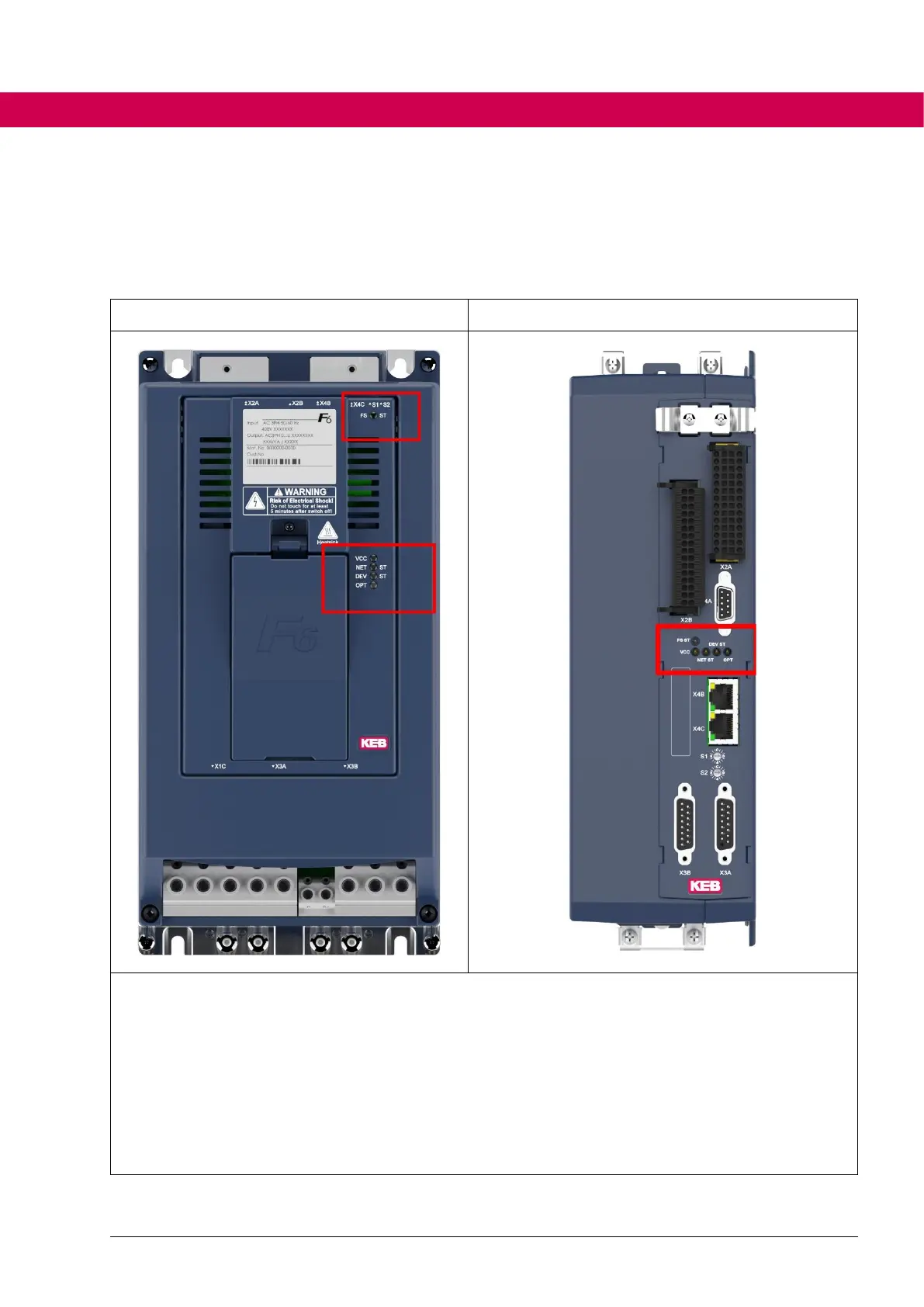
7.5
Status LED
F6 / S6 controls have 4 (c
ontrol type K) or 5 (c
ontrol type A or P) s
tatus LEDs on
the top
View COMBIVERT F
6
View COMBIVERT
S6
FS ST:
Safety status (only for control type A or P)
VCC:
V
oltage sup
ply
NET ST
:
Network
/ fieldbus state (e
.g. CAN,
EtherCAT, VARAN, …)
DEV ST
:
Inverter / unit status Status
(OK, error, wi
thout power s
upply)
OPT:
for optional funct
ions
477
479
Table of Contents
Main Page
Preface
3
Signal Words and Symbols
3
More Symbols
3
Laws and Guidelines
4
Warranty
4
Support
4
Copyright
4
Table of Contents
5
Basic Safety Instructions
14
Target Group
14
Validity of this Manual
15
Electrical Connection
16
Start-Up and Operation
16
Product Description
17
Product Features
17
Functional Overview
17
Used Terms and Abbreviations
18
Table 3-1: Used Terms and Abbreviations
19
Motion Control
20
State Machine
20
Figure 1: State Machine
20
Changes of the State Machine
23
Control Word
24
Statusword
26
Display of the Actual State
27
Affect the Behaviour of the State Machine
28
Brake Control
30
Specification Brake Control F6-A / S6-A or F6-P S6-P
30
Specification Brake Control F6-K / S6-K
30
Functionality
31
Figure 2: Function Brake Control
31
Characteristics of the Brake Control
32
Influence of the Brake Control on the State Machine
35
Times of the Brake Control
35
Status of the Brake Control
35
Errors and Warnings
37
Errors
37
Figure 3: Process of a Fault Reaction
46
Figure 4: Example Co63
49
Automatic Reset of Errors
50
Warnings
51
Protection Functions
54
Overload (OL)
54
Figure 5: OL-Counter
54
Figure 6: Overload Characteristic
55
Overload Power Components (OL2)
56
Figure 7: Overload (OL2) Limiting Characteristic
57
Figure 8: Increase OL2 for 60A Rated Current and 40°C
59
Figure 9: Characteristic of the Current Limit in Relation to the Time
61
Overtemperature Heatsink (OH)
62
Figure 10: Overtemperature Heatsink (OH)
63
Overtemperature Unit (OHI)
64
Overtemperature Motor (Doh)
65
Figure 11: Sensor Calculation by Excel
67
Motor Protection Switch OH2
68
Figure 12: Tripping Motor Protection Switch
69
Figure 13: Dependence of the Motor Protection Function
70
Figure 14: Dependence of the Tripping Time
70
Figure 15: Determination of the Motor Protection Function Data from the Characteristics of the
71
Fieldbus Watchdog
72
Maximum Current
73
Effective Motor Load
74
Figure 16: Effective Motor Load
74
Maximum Acceleration or Deceleration
75
Monitor the Speed Difference
75
External Error / Warning Triggering
77
Safety Stop from Safety Module
77
Error Underpotential (up / Puready)
78
Overvoltage
82
Table 4-1: Overvoltage Level
82
Table 4-2: Permanent Damage Due to Overvoltage
82
Overspeed (ERROR Overspeed / ERROR Overspeed (EMF))
83
Encoder Monitoring
84
Limit Switch
85
Input Phases Failure Detection
88
Figure 17: Limit Switch
88
Motor Phase Failure Detection
89
UPS Mode (Not Available for Compact Cards)
92
Power off Function
92
Figure 18: Motor Operation
93
Figure 19: Regenerative Operation
94
Figure 20: Motor Operation Without Power-Off Function
94
Figure 21: Regenerative Operation in Case of Mains Power Failure
95
Figure 22: Control to Constant DC Link Voltage
95
Figure 23: Circuit Diagram of the DC Control (Ppz=Number of Pole Pairs)
100
Minimum Switch-Off Times
101
Blockade Handling
103
Monitoring of the Load
108
Quickstop
113
Minimum Current Monitoring in the Safety Module
113
Figure 24: Minimum Current Course
115
Braking Transistor
116
Braking Transistor Handling
116
Table 4-3: Switching Threshold for Braking Transistor
117
Braking Transistor Protective Functions
119
Power and Temperature Calculation at the Braking Resistor
120
Sub-Mounted Braking Resistor Protection
121
Fan Control
123
Fan Control F6
123
Fan Control S6-A / S6-K
124
Terminals Short Circuit Protection
124
Control Type K
124
Control Type a
124
Control Type P
125
Operating Modes
126
Operating Mode 1: Profile Position Mode
127
Figure 25: Profile Positioning Mode (1)
128
Figure 26: Profile Positioning Mode (2)
129
Figure 27: Single Positioning
129
Figure 28: Multi Positioning
130
Figure 29: Restart of a Positioning
130
Figure 30: Ramps in Profile Position Mode
136
Figure 31: Motor Encoder with Initiator at Rotary Table
140
Figure 32: Motor Encoder with Encoder and Initiator at Rotary Table
141
Figure 33: Operation with Motor Model and Encoder with Initiator at Rotary Table
141
Operating Mode 2: Velocity Mode
142
Figure 34: Velocity Mode - Overview
142
Figure 36: Target Speed Limitation
143
Figure 37: Ramp Generator
144
Figure 38: S-Curve Type = 0: Continuous S-Curve
148
Figure 39: S-Curve Type = 4: Abort in S-Curve
148
Figure 40: Pass Zero Type = 0: Not Zero
149
Figure 41: Pass Zero Type = 8: Zero
149
Figure 42: Calculation Example
150
Operating Mode 6: Homing Mode
151
Figure 43: Homing - Method 1
154
Figure 44: Homing - Method 2
155
Figure 45: Homing - Method 3 and 4
155
Figure 46: Homing - Method 5 and 6
156
Figure 47: Homing - Method 7 to 14 (23 to 26)
157
Figure 48: Homing - Method 33 and 34
158
Cyclic Referencing
161
Operating Mode 8: Cyclic Synchronous Position Mode
163
Figure 49: Cyclic Synchronous Position Mode - Overview
163
Figure 50: Cyclic Synchronous Position Mode
164
Figure 51: Example Interpolation
165
Figure 52: Position Precontrol
167
Operating Mode 9: Cyclic Synchronous Velocity Mode
168
Figure 53: Cyclic Synchronous Velocity Mode - Principle
168
Figure 54: Cyclic Synchronous Velocity Mode
169
Operating Mode 10: Cyclic Synchronous Torque Mode
172
Figure 55: Cyclic Synchronous Torque Mode - Overview
172
Figure 56: Transfer Torque Setpoint Telegram -> Current Controller
176
Figure 57: Torque Control and Overspeed Interception
177
Operating Mode -2: Jog Mode in the CM Customer Modes Group
178
Figure 58: Operating Mode Jog Mode
178
Figure 59: Drive Profiles in Jog Mode
182
Operating Mode-Independent Functions
184
Figure 60: Torque Limit in All Quadrants
185
Synchronisation
187
Synchronous Time
187
Optimizing the PLL
188
Display Parameters
189
Overview of the Ru Parameters
189
Speed Displays
193
Figure 61: Auxiliary Representation for the Calculation of Ru83[]
194
Position Displays
195
DC Link Displays
196
Current Displays
196
Torque Displays
196
Power/Energy Displays
197
Status Displays
198
Ru75 Global Drive State
198
Ru76 Drive State
202
De115 Global Drive State Mask
205
Figure 35: Velocity Mode
205
Ru30 SACB Comm State
206
Operating Hours Counter
208
Real Time Clock
208
System Counter
208
5.10 Error Displays and Counter
209
Error / Warning Displays
209
Error Counter
209
Error Memory
210
5.11 Inverter Data
211
Product Code
212
Device Type, Software Version and Date
213
Power Unit Identification
215
Serial Numbers
216
Motor Control
217
Interface to the Encoder
217
Terms and Definitions Used here
217
Encoder Types
218
Figure 62: Order Designation
220
Figure 63: Structure Data Word Biss
222
Table 6-1: Selection of Tested Encoders
224
Position Resolution of Different Encoder Types
228
Scan Time Snd Speed Fluctuations
230
Status Parameters of the Encoder Interface and Encoder
232
Parameters for the Encoder Adjustment
233
Figure 64: Distance-Coded Reference Marks at Heidenhain
240
Figure 65: Distance-Coded Reference Marks
241
Operation of Absolute Linear Encoders
251
Operation of Non-Absolute Linear Encoders (with and Without Reference Marks))
254
Operation of Endat Multiturn Encoders with Battery Buffering
255
Error and Warning Messages
256
Store Data in the Encoder
264
Encoder Serial Number
266
Assignment of the Encoder Channels
267
Motor Parameterization
268
General
268
Asynchronous Motor
270
Figure 66: Equivalent Circuit Diagram Motor
271
Synchronous Motor
278
Figure 67: Equivalent Circuit Diagram Synchronous Motor
279
Structure Overview
295
Figure 68: Structure Overview Motor Model
295
Magnetizing Current
299
Figure 69: Generation of the Magnetizing Current
300
Figure 70: Generation of the D-Component
301
Current Control
304
Measurement / Model Currents
307
Currentlimitations
309
Torque Adjustment
310
Figure 71: Procedure of the Offset Measurement
313
Figure 72: Simplified Representation of the Torque Offset Compensation
317
Field Weakening
318
Figure 73: Field Weakening Range Asynchronous Motor
319
Figure 74: Maximum Voltage Controller
321
Figure 75: Limit Value at Synchronous Motors
322
Figure 76: Maximum Torque Depending on the DC Link Voltage for the Synchronous Motor
324
Figure 77: Adjustment of the Torque Limiting Characteristic
325
Figure 78: Limit Characteristic Curve
327
Figure 79: Safety Distance to the Limit Characteristic
328
Flux Controller (ASM)
329
Figure 80: Flux Controller (ASM)
329
Adaption
330
Saturation Characteristic (SM)
331
Figure 81: Torque Constant Depending on the Active Current
332
Cogging Torque Compensation (SM)
334
Control Mode (with Encoder / Encoderless)
335
Figure 82: Cogging Torque Compensation
335
Figure 83: V/F - Influence of the Additional Setpoint
341
Figure 84: V/F - Influence of the DC Link Voltage Compensation
342
Figure 85: V/F - Influence of the Maximum Degree of Modulation
342
Figure 86: V/F - Influence of Dr48 V/F Characteristic Mode
343
Model Control (ASM and SM)
345
Figure 87: Model Deactivation Depending on the Motor Type
348
Figure 88: Model Deactivation Depending on the Motor Type
349
Figure 89: Model Deactivation Depending on the Motor Type
350
Figure 90: Torque Limit Depending on the Setpoint Value
353
Figure 91: Stabilisation Current Depending on Speed
354
Figure 92: Model Stabilisation Term Depending on Motor Speed
355
DC Link Voltage Compensation
357
Identification
358
Deadtime Compensation
367
Switching Frequency Adjustment and Derating
372
Interrupt Structure of the Software
374
Figure 93: Time Allocation
374
Hardware/Software Current Control
380
Sinus Filter
380
Figure 94: Connection Example Sinus Filter
381
Speed Search
386
Protection Functions (Ramp Stop, Current Limitation in Open-Loop (V/F) Operation)
386
DC Braking
389
Figure 95: Motor De-Excitation Time ASCL
393
Speed Controller
395
Overview
395
Figure 96: Speed Controller Overview
395
PI-Speed Controller
396
Figure 97: Pi-Speed Controller
396
Variable Proportional Factor ((System Deviation)
398
Figure 98: Variable Proportional Factor
398
Variable Proportional/Integral Factor (Speed)
399
Figure 99: Variable Proportional Factor (Kp) / Integral Factor (Ki) with Cs08=10%, Cs09=20
399
Speed Controller Adjustment Via Process Data
400
Determination of the Mass Moment of Inertia
401
Figure 100: High-Run Test with COMBIVIS
401
Speed Controller PT1 Output Filter
402
Figure 101: PT1 Output Filter
402
Torque Precontrol
403
Figure 102: Torque Precontrol Mode 1
403
Figure 103: Torque Precontrol Mode 2
404
Figure 104: Torque Precontrol Smoothing
405
Figure 105: Not Linear Torque Precontrol
407
Speed Setpoint Deceleration
410
Figure 106: Overshoots in the Speed Setpoint
410
Figure 107: Speed Setpoint Deceleration
410
Figure 108: Optimal Precontrol Behaviour
411
Torque Limits
412
Physical Torque Limits
412
Figure 109: Torque Limit in the Lower Speed Range
412
Application-Dependent Torque Limits
413
Position Control
415
Position Values
415
Figure 110: Position Control Overview
416
Position Control Mode
418
Position Controller
418
Figure 111: KP Reduction in the Position Controller
420
Following Error
421
Structure Position / Speed Control
422
Figure 112: Structure Position / Speed Control
422
7 I/O Functions
423
Digital Inputs
423
Overview
423
Figure 113: Digital Inputs Block Diagram
423
Terminal State
424
Selection of the Input Source
425
External Setting of the Input State
426
Inversion of the Digital Input State
426
Filter for the Digital Inputs
427
Controlword Inputs CW 1 / CW 2
427
Figure 114: Filter of the Digital Inputs
427
Figure 115: Filter of the Digital Inputs 2
427
Figure 116: Di28 Cw Input 1
429
Figure 117: Ds61: Cw Input 1
429
Overview of the Evaluation of Digital Inputs
431
Figure 118: Structure: Evaltuation of the Digital Input Status
431
Functions of the Digital Inputs
432
Figure 119: Digital Input Controlword
434
Figure 120: Digital Input Controlword
437
Figure 121: Example for the Index Filter
443
Figure 122: Example Index Generation with Edge-Active Strobe
444
Figure 123: Overview Index Generation with Filters and Strobe
445
Overview of the Input Functions
446
Digital Outputs
448
Control Type K (COMPACT)
448
Control Type a (APPLICATION)
448
Control Type P (Pro)
448
Functional Overview
449
Display Internal Digital Outputs
449
Figure 124: Digital Outputs Block Diagram
449
Source Selection for the Digital Outputs
450
External Setting of the Output State
452
Output Signal Generation
452
Figure 125: Comparator Level
453
Function Blocks
454
Figure 126: Filter for the Comparison Operation
460
Variable Operands (Not Available for Compact Cards)
461
Generation of the Linked Function Blocks
462
Generation of the Internal Outputs
463
Inversion of the Digital Output State
465
Overcurrent of the Digital Outputs
465
Analog Inputs
466
Overview of the Analog Inputs
466
Interface Configuration
466
Figure 127: Analog Inputs Block Diagram
466
Input Level of the Analog Inputs
467
Calculation of REF and aux
468
Mapping of REF and aux
469
PID Process Controller
470
Figure 128: PID Controller
471
Analog Output
477
Hardware Analog Output
477
Virtual Analog Outputs
477
Status LED
478
Function of the Status Leds When Switching on
479
Fieldbus State (NET ST)
480
Drive Controller State (DEV ST)
480
FS Status (Control Type a and P)
480
Timer
481
Function of Timer / Counter Blocks
481
Number of Timers
481
Parameter
482
Overview
482
Configuration of the Counting Unit
483
Selection of the Start Bit
483
Selection of the Reset Bit
484
Selection of the Count Event
484
Selection of the Bit for Reversing the Direction of Rotation
485
Evaluation of the Counter
485
Overview of the Counter Structure
486
Figure 129: Timer / Counter Structure
486
Object Directory
487
Glossary
487
Display of Parameters in COMBIVIS 6
488
For Information on How to Connect to the Different Object Dictionaries on a KEB Device, See Chapter 9.5
488
Communication in this Manual
489
KEB Specific Parameters and Standard - Conform Parameters
489
Figure 130: Display Object Data in COMBIVIS
489
Ethercat Conform Parameters
490
Canopen Conform Parameters
490
Figure 131: Interpolation
492
Parameter Conform to Other Fieldbus System Standards
493
Volatile and Non-Volatile Parameters in the Object Dictionary
494
Save Mode and Status of the Non-Volatile Memory
495
Resetting of the Non-Volatile Parameters
496
Figure 132: Loading of Default Values in Download Lists
496
Checksum
497
User Parameters
497
Return Codes at Parameter Accesses
498
10 Communication
500
Communication Interfaces
500
10.2 Diagnostic Interface
501
Configuration of the Diagnostic Interface on the Devices of Control Type P
501
Configuration of the Diagnostic Interface on the Devices of Control Type a and K
506
Communication Modes
508
10.3 Fieldbus Interface
509
General Information about the Fieldbus Interface
509
Use of KEB Diagnostic Tools Via the Fieldbus Interface
509
10.4 COMBIVIS 6 Process Data Assistant
510
Process Data Assistant for VARAN
510
Figure 133: Process Data Assistant for VARAN
510
Process Data Assistant for Ethercat
511
Process Data Assistant for CAN
511
Figure 134: Process Data Assistant for Ethercat
511
Figure 135: Process Data Assistant for CAN
511
10.5 Connection to the File System
512
FTP Connection Set-Up
512
Figure 136: Set the Baud Rate
512
Figure 137: Disconnect the Connection to the Inverter
513
Figure 138: Connect Drive Controller
513
Figure 139: Copy Recipe
513
11 Special Functions
514
Compatibility Objects
514
Power Limitation
515
Liquid Cooling Management
516
PI Controller
516
Figure 140: Overview Controller
516
Figure 141: Overview Controller Motor Cooling
517
Manual Setting
518
Pwm
518
Figure 142: Structure PWM for Cooling Control
518
Signal Output
520
12 Safety Modules
521
Fsoe Watchdog Time Type 3 (Only F6-A / S6-A)
521
Fsoe Watchdog Time Type 5 (Only F6-P / S6-P)
521
12.3 Safety Module Objects
521
12.4 Safety Module Diagnostic Objects
527
12.5 Safety Module Statusword
531
Recipe Management (Storage of Parameter Files in the Drive Controller)
532
Definition of Terms
532
13.2 Basic Function
532
Contents of the Configuration Lists
532
Storage / Identification of the Recipes
532
Limitations
533
13.3 Parameter Structure
534
Parameter "Recipe Options
534
Input-Coded Recipe Selection
534
Binary Coded Recipe Selection
535
Parameter "Start Recipe
536
Parameter "Recipe Status
536
13.4 Operating Conditions
538
14 Annex
539
Inverter Parameters (Address / Resolution /Type)
539
14.2 History of Changes
540
Other manuals for KEB COMBIVERT F6
Instructions For Use
104 pages
Instruction Manual
48 pages
Related product manuals
KEB COMBIVERT H6
40 pages
KEB COMBIVERT S6 Series
82 pages
KEB F6 Series
56 pages
KEB COMBICONTROL C5
28 pages
KEB COMBIVERT F6 Series
92 pages
KEB COMBIVERT F5
196 pages
KEB COMBIVERT F0
138 pages
KEB COMBIVERT F4-C
30 pages
KEB COMBIVERT F5 MULTI
378 pages
KEB COMBIVERT F5 Servo
378 pages
KEB COMBIVERT F5 Series
72 pages
KEB COMBIVERT Series
14 pages

 Loading...


