Safety module diagnostic objects
12.4 Safety module diagnostic objects
For the diagnosis of safety-relevant errors, certain parameters of the safety modules (3
and 5) are available and readable in the Combivis parameter group "sm: safety module
parameters". Furthermore, it is possible to set a defined reaction to "STO" and "Fail Safe"
in the drive controller. These objects and functions require prior knowledge of the con-
tents of the safety module manuals and the handling of the safety modules in COMBIVIS.
➢ The following objects (sm group) are currently only available for safety mod-
ule types 3 and 5. For other types, these objects are either not displayed or
filled with a "0" (e.g. for type 1).
➢ Furthermore, the objects (sm group) shall not be used for safety-related/criti-
cal functions. They are only used for diagnostic support in case of problems
and errors.
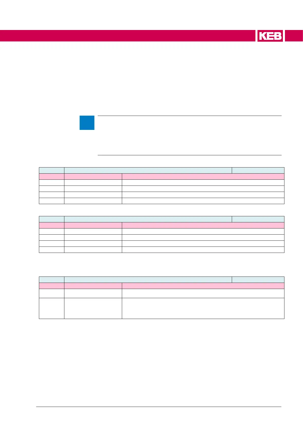
inverter reaction in case of "fail safe“
If fail safe is active, error "140: ERROR Fail Safe" is set.
If fail safe is active, the warning "fail safe" is set.
inverter reaction in case of "STO“
If STO is active, error "139: ERROR STO“ is set.
If STO is active, the warning "STO" is set.
The drive controller provides an object in which the customer can configure a visual re-
sponse to a triggered error by STO or Fail Safe. The ("OPT") LED (red) on the control
boards is used for this.
opt. inverter reaction in case of "STO” or “fail safe”
There is no optical response in case of "Fail Safe" or STO.
If a warning or error message has been configured as response to
"STO" or "Fail Safe" and this bit is active, a red LED (->"OPT" LED)
at the inverter starts to light up (see 7.5 Status LED).
The error and warning information for STO or Fail Safe are also available in the do pa-
rameters for switching an output.
The following table shows the safety module-specific diagnostic parameters. These are
read out from the safety module via an internal communication channel and correspond
to the parameters that are visible in the Safety Wizard. They are for diagnostic purposes
only. Subindices 1 to 14 are identical for safety modules 3 and 5. Subindices 15 to 18 are
only available in safety module 5.

 Loading...


