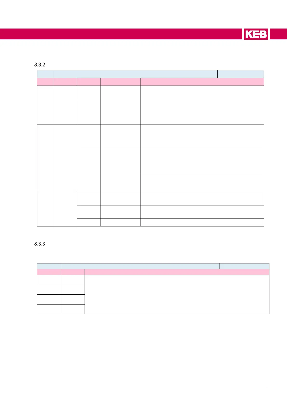
Configuration of the counting unit
The counter operates as timer
Input is the ms grid
The counter operates as event counter
Input is an edge of an input bit
(Definition of the bit with do37 count source bits,
Definition of the edge with bit 5/6 of this parameter)
The inverted enable signal is simultaneously the reset.
The counter counts events or time as long as the ena-
ble bit is set. If the enable bit is omitted, the counter is
stopped and reset to zero
The counter counts events or time as long as the ena-
ble bit is set. The omission of the enable signal stops
the counter. The counter can only be "set to zero" via
the additional reset input
If the counter has been started by the enable signal, it
can only be stopped again and simultaneously set to
zero by the separate reset input
positive edges are counted
negative edges are counted
Selection of the start bit
In the array do32 run source parameter the parameters are defined to taken the enable /
start bit of the counter. Subindex 1 defines counter 1, subindex 2 defines counter 2.
Selection of the parameter, which bits can start or release the counter
ru88: Bit 0 = F1 / Bit 1 = F2 /.. / Bit 8 = CF1 / .. / Bit 11 = CF4
ru19 / ru20: Bit 0 = O1 / .. / Bit 3 = O4 / Bit 4 = OA / .. / Bit 6 = OC / Bit 7 = Relay
ru18: Bit 0 = I1 / .. / Bit 7 = I8 / Bit 8 = IA / .. / Bi11 = ID /
Bit12/13 = CW1/CW2 / Bit 14/15 = STO1/STO2

 Loading...


