• The modulation is released (in default setting) with co00 = 3 and then co00
= 11 and the drive starts the identification. The progress of the identifica-
tion can be tracked in dr55 ident state. Some steps may take a few
minutes. The final state should be dr55 = 14 "ready“. The type of error can
be found in dr57 ident error info if the identification ends in 12 "error“ (=>
Description of dr57 in Chapter 6.2.18 Identification).
• Lock the modulation again (co00 = 0).
• Deactivate the identification with dr54 = 0 and store the identified data with
dr99 = 0. By way the controller are parameterized.
Application-specific data
The following items are not complete, but these values must be checked at least.
base is operating mode velocity mode.
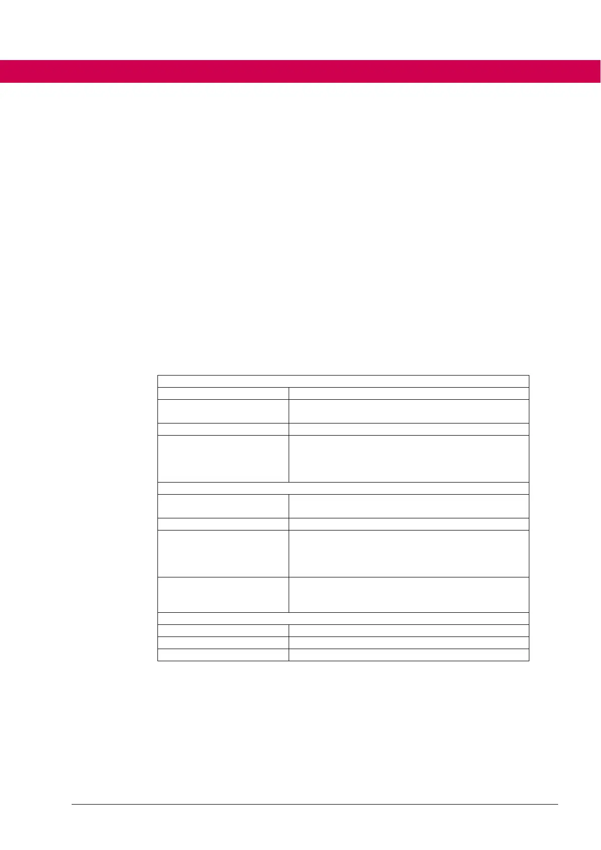
Speed limits
Speed limits can be parameterized in the vl parameters for the velocity mode
Torque limit of the motor
Torque limit of the application (is valid in all quad-
rants)
Torque limits for the single quadrants
Torque for the definition of the speed-dependent
limiting characteristic. This value must be in-
creased, if the torque reduction according to a
1/x^2 characteristic starts to early.
de29 inverter maximum
current
only display / maximum current for control
Maximum current of the motor
The maximum current of the inverter can be de-
creased here (e.g., if the limit for the control should
be lowered at motors with high current ripple in or-
der to avoid overcurrent errors)
Setting of the maximum current for control (defines
the safety distance to the overcurrent switch-off
threshold)
Values for acceleration / deceleration
Values for the jerk in different ramp phases
General parameterization of the ramp generator

 Loading...


