Synchronous motor
6.2.3.1 Nameplate data
The rated motor data are entered in this objects.
If motor inertia can be taken from the data sheet this value should be entered in
dr32.
If the motor inertia is unknown, cs17 can be set to 0 and instead the total inertia of
the motor plus all rigidly coupled inertia can be entered in parameter dr32 (=> also
6.3.6 Determination of the mass moment of inertia).
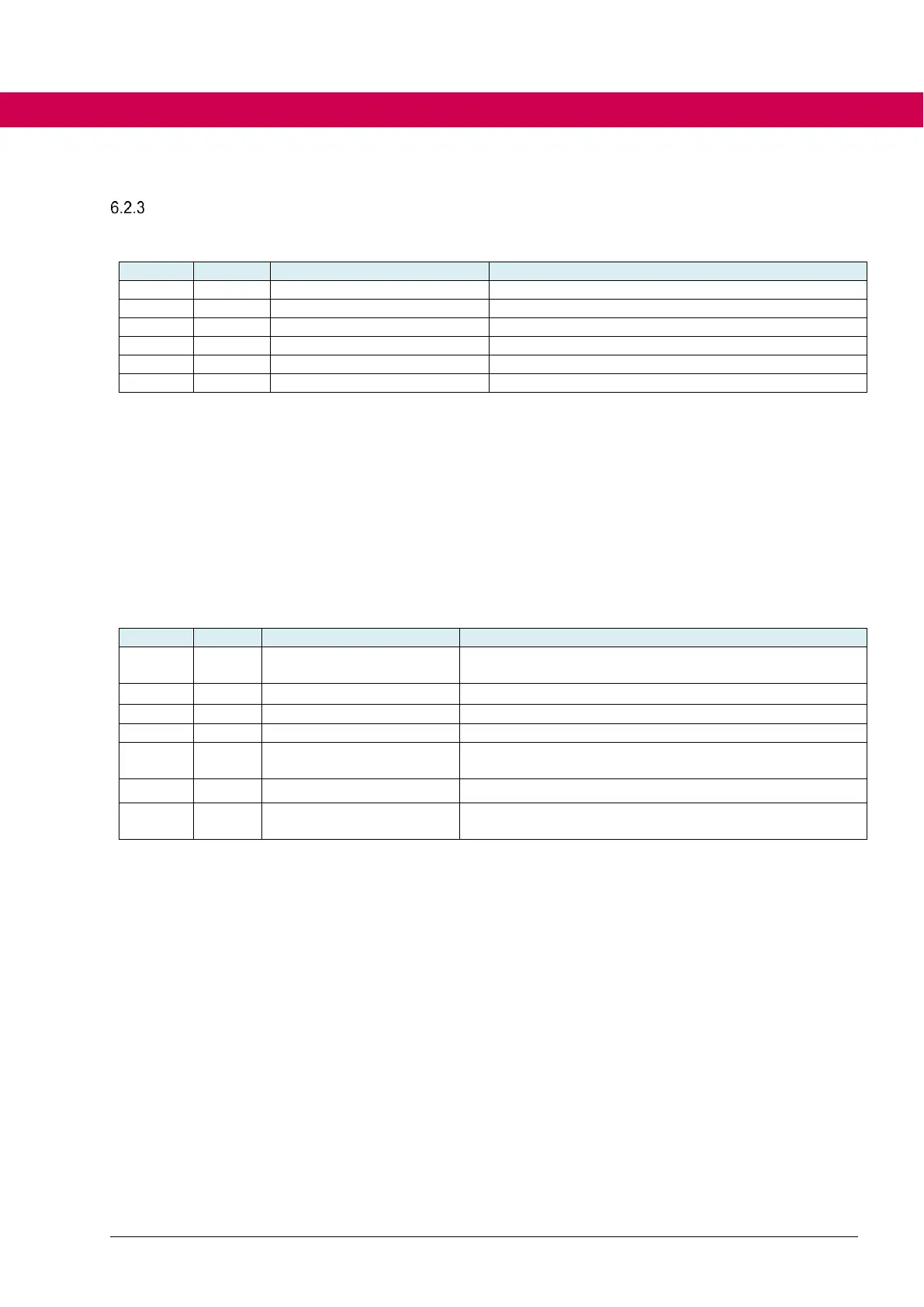
6.2.3.2 Equivalent circuit data
EMC (peak value of the phase-to-phase voltage) at 1000
rpm in V
Cross inductance (inductance q-axis) in mH
Series inductance (inductance d-axis) in % of dr15.
Speed when EMC is identified (automatically preset) in
% of rated speed
Starts the identification
Displays current measurement or status message
(e.g. "stator resistance“ "ready“ or "error“)
Parameters dr14, dr15, dr16, dr17 can be taken from a data sheet or automatically
determined by the identification.
Mostly only one incuctance is given in the data sheet. This means, series and
cross inductance are identical. Then the inductance value must be entered in dr15
and dr16 must be set to 100%.
For identification of the EMC the motor must be able to turn freely without load.
The speed for identification is determined by dr44. This value must only be ad-
justed if the application only allows low speed (e.g.). With the identification steps at
standstill the motor can be moved easily by the test signals.

 Loading...


