6.2.10.3 Maximum voltage
6.2.10.3.1 Maximum output voltage
The output voltage of the inverter is generated by a pulse-width modulation of the
DC link voltage.
A modulation factor of 100% means, that the amplitude of the motor voltage
(phase-phase voltage) is equal to the DC link voltage.
The effective value of the motor voltage can be increased over 100%, however the
output voltage differ from the sinusoidal form.
Therefore additional harmonics occur at a modulation factor over 100% that gener-
ate oscillating torque or additional losses in the motor. The voltage distortion from
approx. 103% often effects unsmooth motor and control behavior.
Adjustment of max. permitted modulation grade.
6.2.10.3.2 Maximum voltage controller
The maximum voltage controller servers for a reduction of the „counter voltage“ at
asynchronous motor via the flux and at synchronous motor via the reactive current
(Id).
The voltage limitation occurs by flux reduction for the asynchronous machine. The
motor flow can be reduced by the controller to ¼ of the value (according to the
magnetization characteristic).
For the synchronous machine, voltage limitation occurs by providing a negative
magnetization current. The maximum value of this current is defined with parame-
ter fc05 Umax reg. limit.
The controller can only reduce the flow or regulate the Id to negative values.
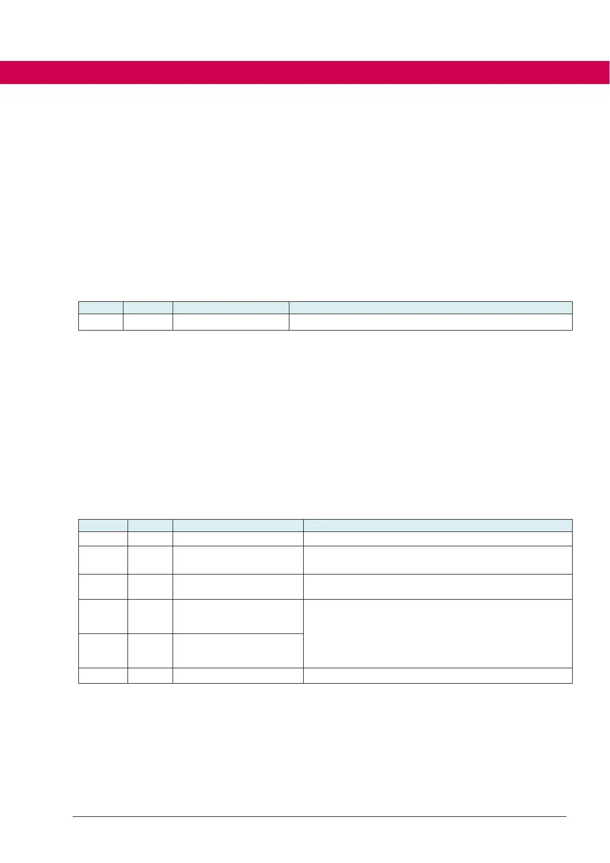
Maximum voltage controller activation
Proportional gain of the controller usually only causes
trouble and should normally remain at 0
Integral gain of the controller
The setpoint for the maximum voltage controller (fc03)
should be at least 2% lower than the maximum modula-
tion grade (fc04).
Higher differences can also be required dependent on
the desired dynamics.
Limit for maximum voltage controller

 Loading...


