The following applies to all control types (A, K, P):
If value 3: 100µs is parameterized as "basic Tp“, value 4: 4xTpBase can also be
selected as time grid for "mid irq“ . The task "mid irq“ is then called every fourth
"basic Tp", i.e. every 400µs.
Applies only to control type P :
For each setting for "basic Tp“, the value "4: 4 x TpBase" can be parameterised
for mid irq. The smallest cycle time of the middle interrupt level is then 250 µs
with the setting basic Tp = 62.5 µs and mid irq = 4 x TpBase.
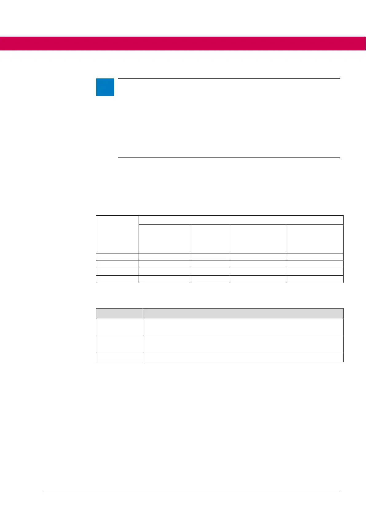
6.2.21.2 Scan times of position, speed and current controller
The following scan times of the internal control circuits also occur by the setting of
is22.
Table with scan times of some functions:
Current control-
ler, motor
model, hf injec-
tion
Speed con-
troller,
position
controller
Digital inputs,
analog inputs,
state machine,
operating modes
Digital outputs,
analog output
Assignment of some functions to the interrupt levels
Assigned functions (selection)
Motor model, current controller, speed controller, position controller,
encoder interface, hf injection
Digital inputs, analog inputs, status machine, operating modes, PDOs,
system counter
Digital outputs, analog output
There is another dependency for the effective controller cycle times: the actual ac-
tive switching frequency (displayed in ru72 act. switch. freq (kHz)).
Although the controller is called in a faster grid, only 2 voltage values per modula-
tion period can be output at a switching frequency of 2 kHz. This means that, de-
spite a current controller cycle of 62.5 µs, the voltage can only be changed every
250 µs (with switching frequency group 0: 62.5 µs).

 Loading...


