Parameter structure for the definition of overcurrent / overvoltage
behaviour
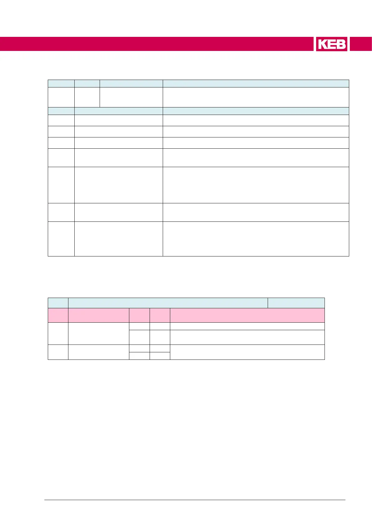
v/f current limit control mode
Current controller access in v/f operating mode
DC link voltage setpoint for the LD (U) stop function
Integral gain factor (KI) for current-dependent change of acceler-
ation / deceleration ramps
Differential + integral gain factor (KD + KI)
Evaluation of the current rise with integration.
The ACC/DEC ramp is also reduced below the current level
Imax
(*1)
depending on the rate of current rise
Integral gain factor (KI) for DC voltage-dependent change of the
deceleration ramps
Differential + integral gain factor (KD + KI)
Evaluation of the voltage rise with integration.
The DEC ramp is also reduced below ds60[3] LD-U stop voltage
level depending on the rate of voltage rise.
(*1)
The maximum current "Imax" is formed from the following parameters: dr12
max. current %, is11 max current [de28%], is35 set current limit, is14 overload pro-
tect mode
v/f current limit control
No current controller active
Current controller becomes active if the activation
condition is fulfilled
Activation if the speed is less than 10% of the rated
speed (dr04 rated speed)
The maximum current is formed from the following parameters: dr12 max. current %, is11 max
current [de28%], is35 set current limit, is14 overload protect mode and (only when DC braking
is active) ds62[4] max.DC current

 Loading...


