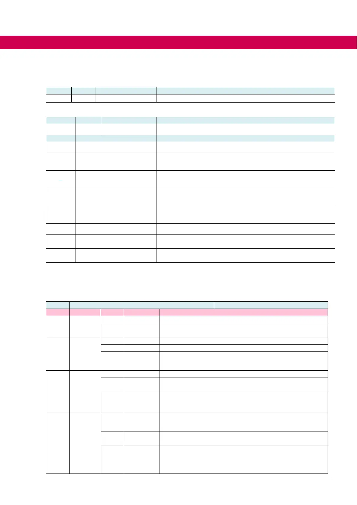
6.2.26.2 Parameter overview
Selection of the inputs that trigger DC braking
Parameter structure for defining the behavior at DC braking
Different modes of braking adjustable
Parameterization of the modulation switch-off time and activation
mode of the DC brake when using a digital input
Display parameter of the hardware-dependent modulation
switch-off time of the device
Current limit to which the higher-level boost controller limits the
motor current, with regard to the rated current of the motor.
Max. DC voltage during DC braking proportionally to the rated
voltage (Un) of the motor
braking speed level [%Nn]
Speed level in % of the rated motor speed to activate the brak-
ing
State of DC braking
0 = ready, 1 = flux reducing, 2 = activ
6.2.26.3 Activation of DC braking
ds62[1] DC braking mode defines the activation and mode of DC braking.
No start by digital input
Start by digital input and additionally dependent on the actual
speed
No status-dependent start
Start in state: “quickstop“, “fault reaction“, “shut down“, “disa-
ble operation active”
Start in state: “quickstop“, “fault reaction“, “shut down“, “disa-
ble operation active” and additionally dependent on the ac-
tual speed.
No ramp state dependent activation of the DC braking
DC braking if decelerated
=> Ramp state “DEC“
Start of DC braking when the target speed (ru05 set value
display) and the actual speed (ru08 actual value) are below
the level (ds62[7] braking speed level [%Nn]). The condition
is that the actual speed has been once above the level.

 Loading...


