184 8163A/B, 8164A/B, 8166A/B User’s Guide
7 Return Loss Measurement
Return Loss Measurement
Patchcord on RL module Output
The front panel connector is angle-polished to minimize reflections. Only
patchcords with angled connectors should used here and care should be
taken to avoid contamination and scratches. A high-quality measurement
patchcord should be used for connection to the device under test to avoid
overly frequent reconnection at the instrument.
Setup
External and Internal Sources
The Return Loss measurement setup described uses:
• A Fabry-Perot laser source module, inserted as a second module in the
same mainframe as the Return Loss module, or
• An internal source.
Making sure all the connectors are clean, set up the instrument as shown
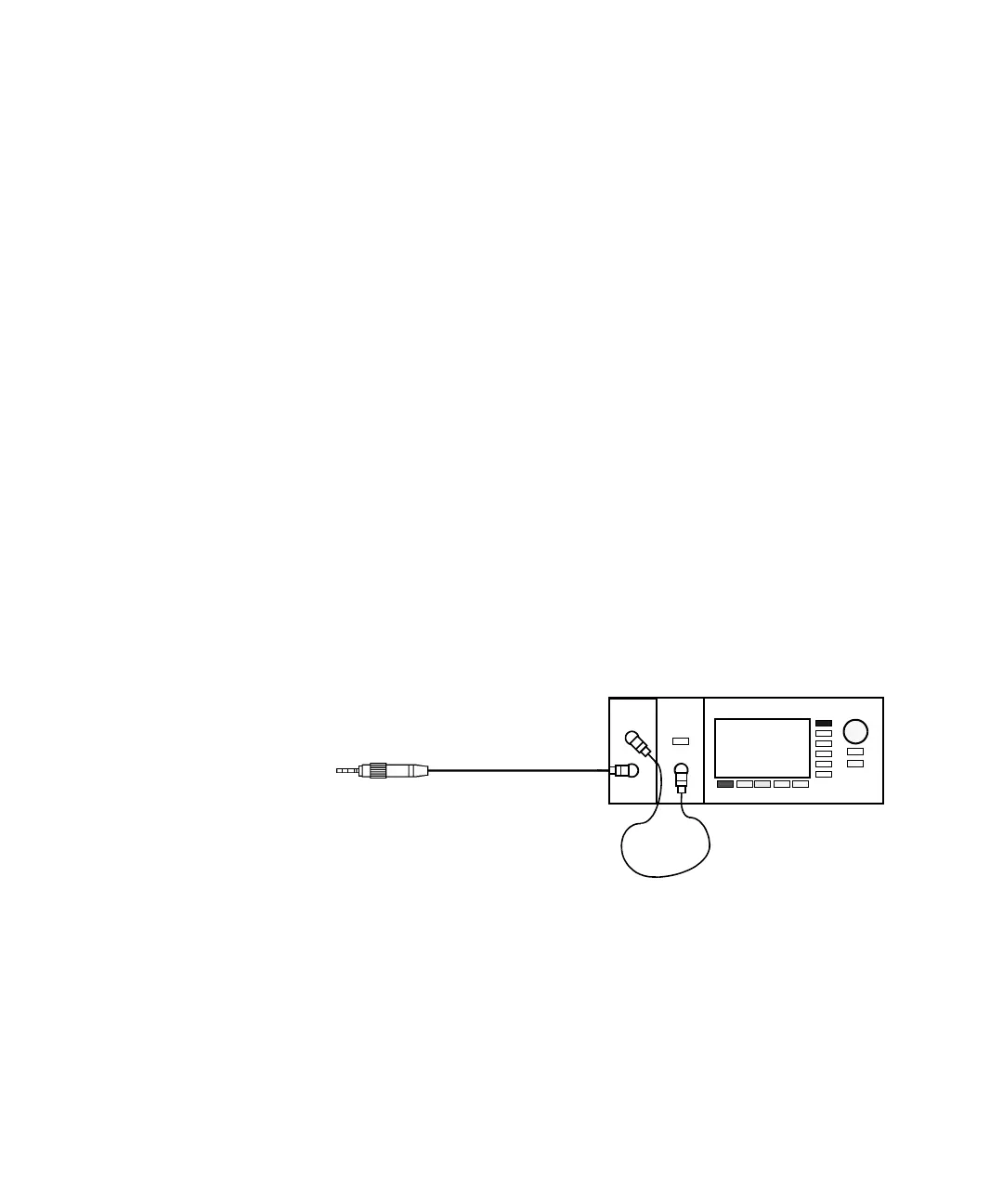
in Figure 102 on page -184 if you are using an External Source.
Figure 102 Return Loss Measurement Setup - External Source used
or Figure 103 on page -185 if you are using an internal source.
8161x 8163B Lightwave MultimeterLaser
Source