8163A/B, 8164A/B, 8166A/B User’s Guide 207
Return Loss Measurement 7
Calculating the Return Loss of the DUT
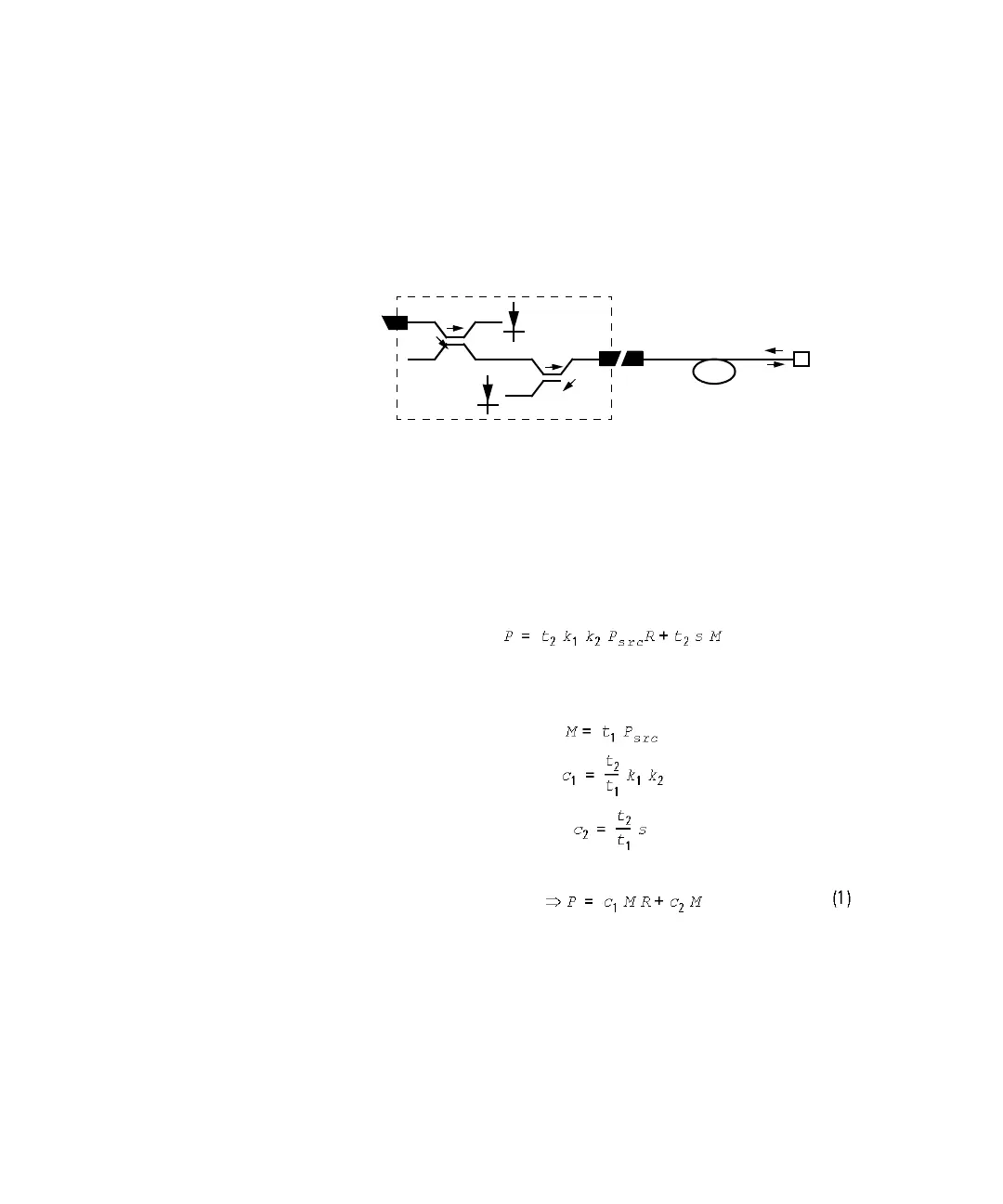
The system may be represented by the general diagram shown below:
The reflected power, measured by the instrument, (P), from the
component with the known reflection factor, is given by the sum of:
• the part of the power, reflected by the component, which is transmitted
through the coupler, and
• the reflections due to the measurement system.
That is:
where:
The constants t
1
, t
2
, k
1
and k
2
are multipliers giving the proportion of
power transmitted through the coupler from the Input port to the Output
port and from the Output port to the sensor port respectively. In other
words, when optical power is input at the Output port, k
2
times that power
is output at the sensor port. It is not necessary to know the value for these
constants, they can be eliminated later.
Reflection-free
Termination
R
M
ref
P
ref
Keysight 81610A
Reflectivity
P
in
P
r
P
src
t
1
k
1
k
2
t
2