198 8163A/B, 8164A/B, 8166A/B User’s Guide
7 Return Loss Measurement
How to Measure Return Loss
It is not necessary to make new calibration measurements for each DUT.
You can make the calibration measurements for your system, and then
measure the return loss of many devices.
The value shown in the result field for the Return Loss channel is the
measured return loss.
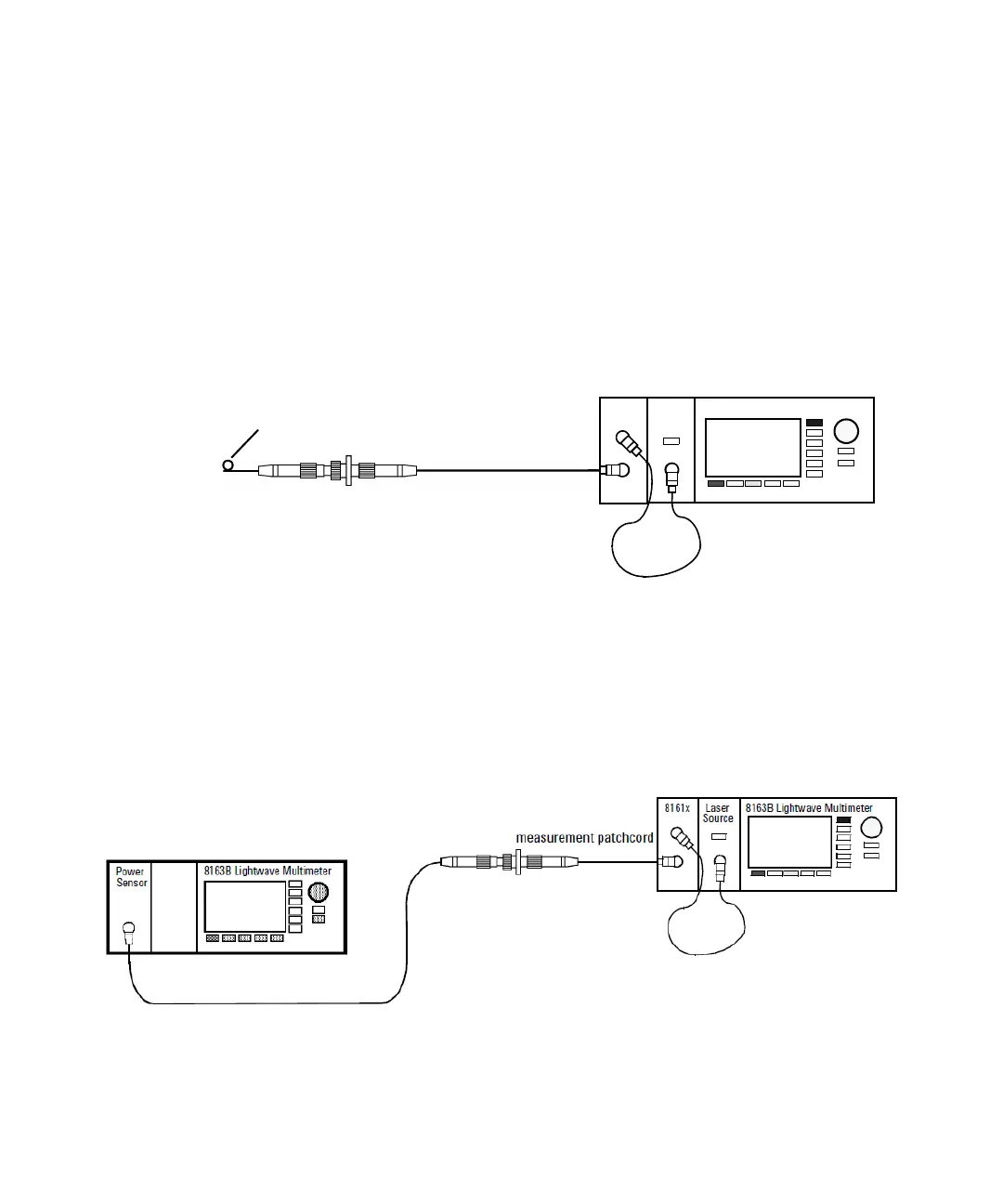
1 Attach the DUT to the measurement patchcord. In the example shown
in Figure 120 on page -198, the DUT is a connector pair.
Figure 120 Measuring the Return Loss of the DUT (in this example: a Connector Pair)
Tip: Terminate your system close to the DUT to make sure that you are
only measuring reflections from the DUT.
Figure 121 Measuring the Power Transmitted through the DUT (a Connector Pair)
Termination
measurement patchcord
8161x 8163B Lightwave MultimeterLaser
Source