222 8163A/B, 8164A/B, 8166A/B User’s Guide
8 Setting Attenuation and/or Power Levels
4 Set the Attenuator module’s λ parameter to the appropriate
wavelength. Set the Attenuator module’s
α parameter, the attenuation
factor, to 0.000 dB.
5 Connect the source output to the Attenuator module input.
6 Use another patchcord to connect the Attenuator module output to
the reference powermeter input.
7 Note the insertion loss measurement displayed by the powermeter.
8 Select the details screen for the Attenuator.
9 Use the cursor key to select the
α
Offset
parameter, then press [Edit].
10 Use the cursor key to enter the insertion loss measured at Step 7, then
press [OK].
11 Disconnect the patchcord from the reference powermeter and connect
it to the DUT input.
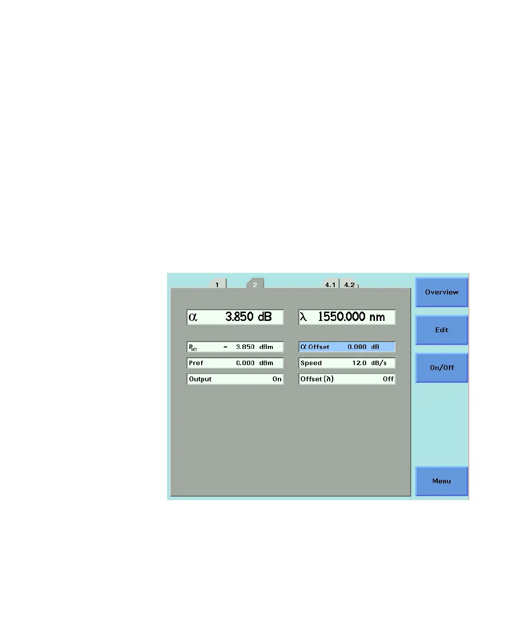
Figure 136 81570A/71A/73A - Attenuation factor applied with no offset
Figure 136 on page -222 shows an attenuation factor α of 3.850 dB
applied with no α
Offset
.