232 8163A/B, 8164A/B, 8166A/B User’s Guide
8 Setting Attenuation and/or Power Levels
During a test that utilizes the λ Offset Table
When the Offset (
λ) feature is on the exact offset applied depends on how
the operating wavelength
λ you set for the Attenuator module relates to
the
λ Offset Table entries, as shown in Figure 140 on page -232.
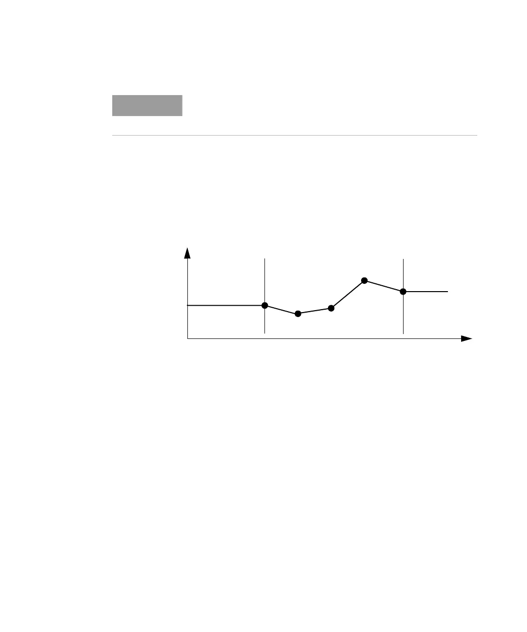
Figure 140 Extrapolation and Interpolation of Offset Values
• If the operating wavelength matches a wavelength stored in the λ
Offset Table, the exact offset value is used. The Attenuator status
display includes ‘Exa’.
• If the operating wavelength is between two wavelengths stored in the
λ
Offset Table, the offset applied is calculated by linear interpolation. The
Attenuator status display includes ‘Int’.
• If the operating wavelength is greater than, or less than, the range of
wavelengths stored in the λ Offset Table, the offset value for the closest
wavelength is extrapolated. The Attenuator status display includes
‘Ext’.
If your Attenuator module is not hosted by the same mainframe as your
reference powermeter you can, at step 7, enter the appropriate Offset
manually.
linear interpolation
extrapolation:
same value for
all l < l
1
l
extrapolation:
same value for
all l > l
n
Offset Value
l
1
l
n